Onboard atomizing cooling system for creating negative pressure environment by virtue of ejector

A spray cooling and ejector technology, applied in cooling/ventilation/heating renovation, electrical equipment structural parts, electrical components, etc., can solve the problems of evaporative refrigeration cycle with cold source, long cold storage time, and inability to put into use at any time.

Pending Publication Date: 2017-12-12
NANJING UNIV OF TECH
View PDF8 Cites 12 Cited by
  • Summary
  • Abstract
  • Description
  • Claims
  • Application Information

AI Technical Summary

Problems solved by technology

[0004] Some patents have proposed the application method of spray cooling in the airborne field. For example, patent ZL201510072716.7 proposes a cooling system based on air expansion refrigeration for airborne heating elements. The main feature is the use of turbines as refrigeration devices and power sources. When this solution is put into use, the turbine cooling storage must be used first for spray cooling, and the cooling storage time is long, so it cannot be put into use at any time; the structure is complex and the equipment space is large, and it is difficult to install on military aircraft
Patent ZL201510074027.X proposes a cooling system and method based on evaporative refrigeration for airborne heating elements. The main feature is that the evaporative refrigeration cycle is used to provide an indirect cold source for the system. After adding the evaporative refrigeration cycle, the volume and energy consumption are very large, and This invention does not equip the evaporative refrigeration cycle with a cold source, and if it is put into actual use, the volume will be larger and cannot meet the requirements of the airborne space

Method used


Image

  • Onboard atomizing cooling system for creating negative pressure environment by virtue of ejector
  • Onboard atomizing cooling system for creating negative pressure environment by virtue of ejector
  • Onboard atomizing cooling system for creating negative pressure environment by virtue of ejector

Examples


Embodiment Construction

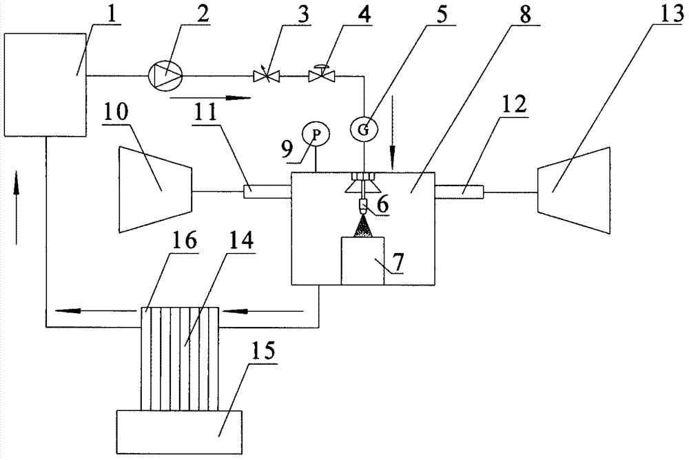
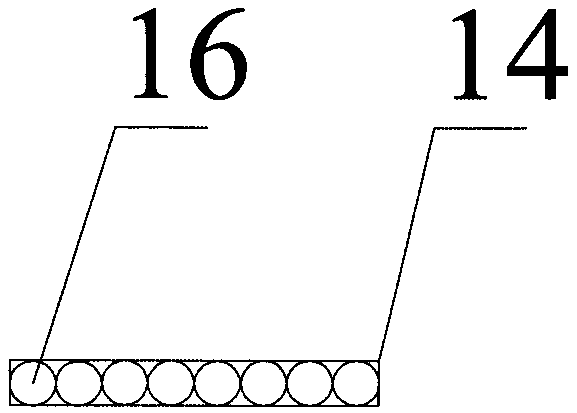
[0028] Such as figure 1 As shown, an airborne spray cooling system using an ejector to create a negative pressure environment mainly includes a water tank 1, a water pump 2, a flow regulating valve 3, a stop valve 4, a flow meter 5, a nozzle 6, a surface to be cooled 7, and a spray chamber 8. Pressure gauge 9, engine exhaust port 10, ejector nozzle section 11, ejector mixing section 12, exhaust port 13, heat pipe heat exchange box 14, external environment port 15, heat pipe 16.

[0029] Before the aircraft takes off, the running time of the spray cooling system is obtained according to the flight duration of the aircraft and the required cooling time of the equipment, and sufficient and quantitative water is provided in the water tank 1 according to the running time. At this time, the flow regulating valve 3' and the shut-off valve 4 are all in the closed state.

[0030] After the aircraft takes off, when the electronic equipment or other surfaces need to be cooled, the shut-...


PUM


Abstract

The invention relates to an onboard atomizing cooling system for creating a negative pressure environment by virtue of an ejector, which belongs to the field of cooling of onboard high heating density equipment, and mainly solves the high heating density continuous heat dissipation problem of the surface of onboard electronic equipment. The onboard atomizing cooling system mainly comprises a water tank (1), a water pump (2), a flow adjusting valve (3), a stop valve (4), a flow meter (5), a nozzle (6), a to-be-cooled surface (7), an atomizing chamber (8), a pressure meter (9), an engine tail gas entraining hole (10), an ejector nozzle section (11), an ejector mixing section (12), a exhausting hole (13), a heat pipe heat exchange box (14), an external environment hole (15) and a heat pipe (16). According to the onboard atomizing cooling system, engine tail gas is taken as an ejection air source, the negative pressure environment is created in the atomizing chamber, the surface of high-temperature electronic equipment is atomized and cooled by virtue of vaporization latent heat of water, and the cooling of the heat pipe and the heat-exchanged water vapor on the surface of the to-be-cooled surface are introduced, so that the closed atomizing cooling system can safely and stably work, has an energy-saving effect and can meet the cooling requirements in onboard complex environments.

Description

technical field [0001] The invention relates to an airborne spray cooling system using an ejector to create a negative pressure environment, belonging to the field of airborne high heat flux equipment cooling. Background technique [0002] With the continuous improvement of aircraft maneuverability, stealth performance and defense performance requirements, airborne electronic components are developing rapidly towards high power, high integration and miniaturization. The heat flux density of the new generation of military electronic equipment is as high as 107W / cm 2 , the heat output of the highest-end processor exceeds 250W / cm 2 . If effective measures are not taken to reduce the surface temperature of electronic equipment, its working efficiency will be greatly reduced, and the electronic devices will be burned, which will affect flight safety. Therefore, how to efficiently and safely solve the problem of rapid heat dissipation of airborne equipment has important researc...

Claims


Application Information

Patent Timeline
Patent Type & Authority Applications(China)
IPC IPC(8): H05K7/20
CPCH05K7/20345
Inventor 王瑜邱兰兰袁晓磊刘金祥周斌蒋彦龙
Owner NANJING UNIV OF TECH
Why Eureka
Try Eureka