Diagnosis device

A diagnostic device and light source technology, which is applied in signal devices, lighting devices, transportation and packaging, etc., can solve the problems of controlling car lights, not being able to diagnose the type of bulbs, etc., and achieve the effect of increasing the service life

Active Publication Date: 2017-12-12
PEZHO SITROEN AUTOMOBILS SA
View PDF6 Cites 2 Cited by
  • Summary
  • Abstract
  • Description
  • Claims
  • Application Information

AI Technical Summary

Problems solved by technology

However, none of these documents are capable of diagnosing the type of light b

Method used


Image

  • Diagnosis device
  • Diagnosis device

Examples


Embodiment Construction

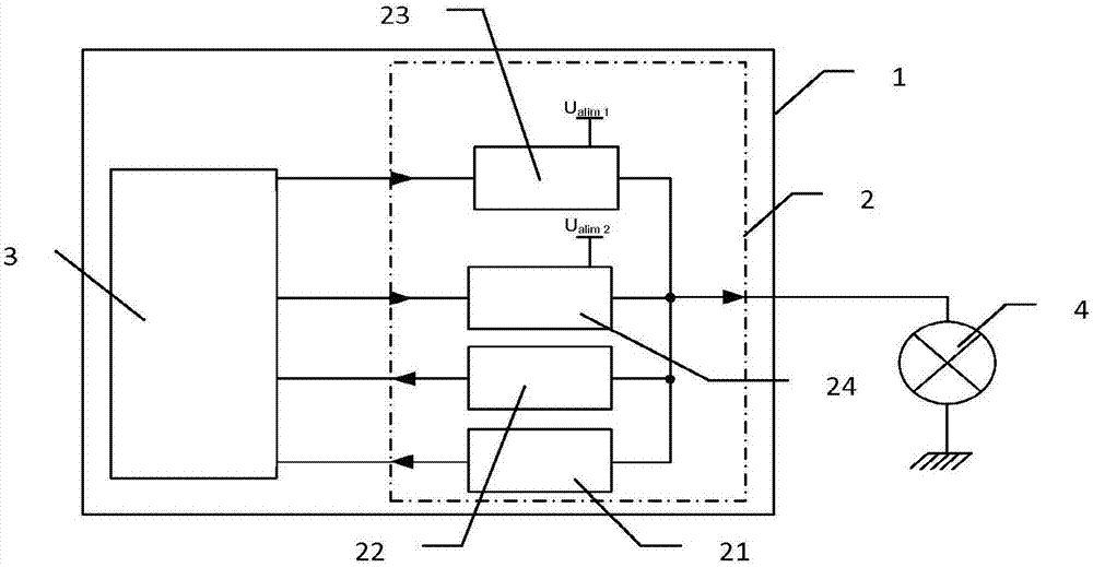
[0021] figure 1 A diagnostic device 1 is shown for diagnosing a detachable light source 4 , for example mounted on a trailer that is configured for attachment to a motor vehicle. The device 1 comprises: a control unit 3 configured for connection with at least one light source 4; and an interface element 2 interfacing with said at least one light source 4, said interface element thus being located between said control unit 3 and said light source 4 . Thanks to this interface element 2 , device 1 is able to detect the type of vehicle light, that is to say the type of said light source 4 , and to carry out an adaptive adaptation of the control of the vehicle light. Note that there are preferably as many interface elements 2 as light sources 4 .

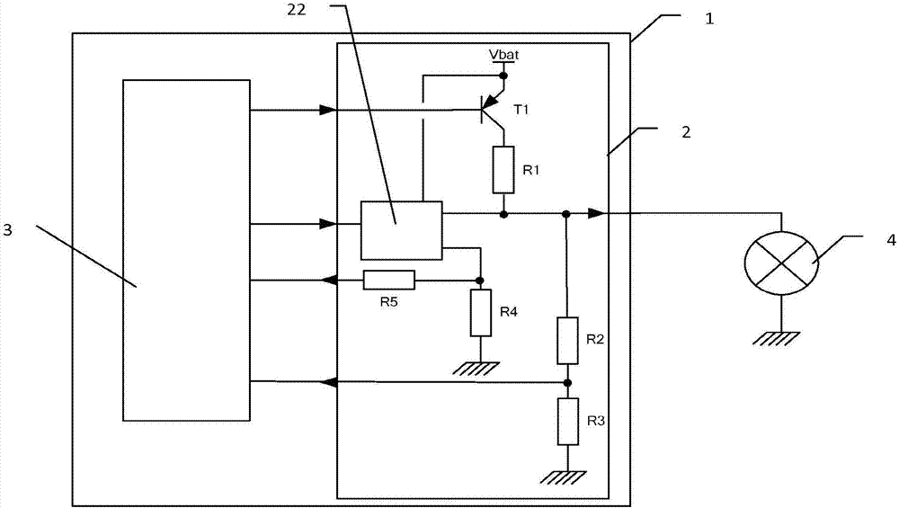
[0022] Such as figure 1 As can be seen above, the interface element 2 preferably comprises a plurality of components 21 , 22 , 23 , 24 in which there is a detection device 21 for detecting the output voltage of the light source 4 . H...


PUM


Abstract

The invention relates to a device (1) for diagnosing detachable light sources mounted on a motor vehicle, comprising a control unit (3) arranged to be connected to at least one light source (4), and an element (2) for interfacing with said at least one light source, characterised in that the interface element comprises a means (21) for detecting an output voltage of the light source, arranged to detect a first output voltage value of the light source and to transmit said first voltage value to said control unit, and in that said control unit is arranged so as to determine a type of light source in accordance with said first voltage value.

Description

technical field [0001] The present invention generally relates to a diagnostic device mounted on a motor vehicle, and more particularly to a diagnostic and control device mounted on a motor vehicle for diagnosing and controlling lights mounted on a trailer. Background technique [0002] As is well known in the state of the art, motor vehicles can be provided for attachment at the rear of a trailer type of accessory, such as a caravan, or a storage box, or of the same kind. Since these trailers usually shade the rear of the vehicle and thus the lights or lighting / signaling devices at the rear of the vehicle, the trailers themselves are usually equipped with substantially the same lighting / signaling devices as the vehicle's Lighting / signaling devices, that is to say these trailers include position lights, rear fog lights, brake lights, turn signals, or reversing lights. [0003] On road vehicles and trailers, filament bulbs are mainly used for lighting / signaling, but increasi...

Claims


Application Information

Patent Timeline
IPC IPC(8): B60Q1/30H05B37/03B60Q11/00H05B44/00
CPCB60Q1/305B60Q11/005H05B47/20H05B45/14
Inventor J·M·戴诺F·德鲁耶F·福雷尔J·P·阿利克斯
Owner PEZHO SITROEN AUTOMOBILS SA
Why Eureka
Try Eureka