Fluid reinforcement structure, one-way valve, intelligent mosquito killing equipment, blow drier, fan and propeller of airplane and ship or submarine

A one-way valve and fluid technology, applied in mechanical equipment, devices for catching or killing insects, electric speed/acceleration control, etc., can solve the problem of increasing the wind pressure at the end of the fan blowing channel

Inactive Publication Date: 2017-12-15
HUNAN QINGCHUANG SCI & TECH CO LTD
View PDF5 Cites 5 Cited by
  • Summary
  • Abstract
  • Description
  • Claims
  • Application Information

AI Technical Summary

Problems solved by technology

The engineers of our company accidentally discovered that making the air flow spiral forward can increase the wind pressure at the end of the fan blowing channel, which solved the problem of the pressure at the end of the fan blowing channel with a solid shaft in the center

Method used


Image

  • Fluid reinforcement structure, one-way valve, intelligent mosquito killing equipment, blow drier, fan and propeller of airplane and ship or submarine
  • Fluid reinforcement structure, one-way valve, intelligent mosquito killing equipment, blow drier, fan and propeller of airplane and ship or submarine
  • Fluid reinforcement structure, one-way valve, intelligent mosquito killing equipment, blow drier, fan and propeller of airplane and ship or submarine

Examples


Embodiment 1

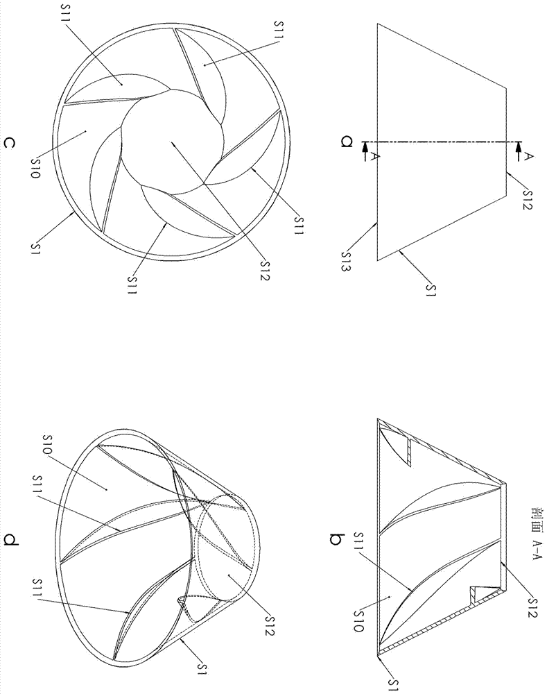
[0052] Implementation example 1, such as figure 1 As shown, the fluid booster structure, S1 is the body of the one-way valve fluid booster structure, S10 is the conical cavity, S11 is the spiral flow guide structure, and S12 is the small end of the conical cavity, which is the one-way valve fluid booster structure S13 is the large end of the conical cavity, which is the fluid inlet of the fluid booster structure of the one-way valve; the spiral guide structure is a spiral plate, the number of spiral plates is 5, and the height of the spiral plate is converted into a coordinate curve as follows: Arc, a line that bends in one direction.

Embodiment 2

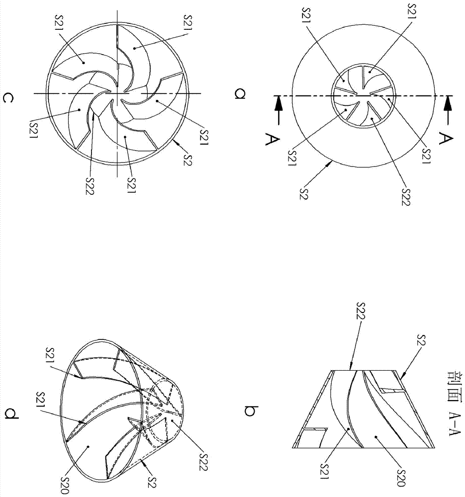
[0053] Implementation example 2, such as figure 2 As shown, the fluid booster structure, S1 is the body of the one-way valve fluid booster structure, S10 is the conical cavity, S11 is the spiral flow guide structure, and S12 is the small end of the conical cavity, which is the one-way valve fluid booster structure S23 is the large end of the conical cavity, which is the fluid inlet of the fluid booster structure of the one-way valve; the spiral guide structure is a spiral plate, the number of spiral plates is 5, and the height of the spiral plate is converted into a coordinate curve as follows: The straight line, that is to say the height of the spiral plate in this embodiment is constant.

Embodiment 3

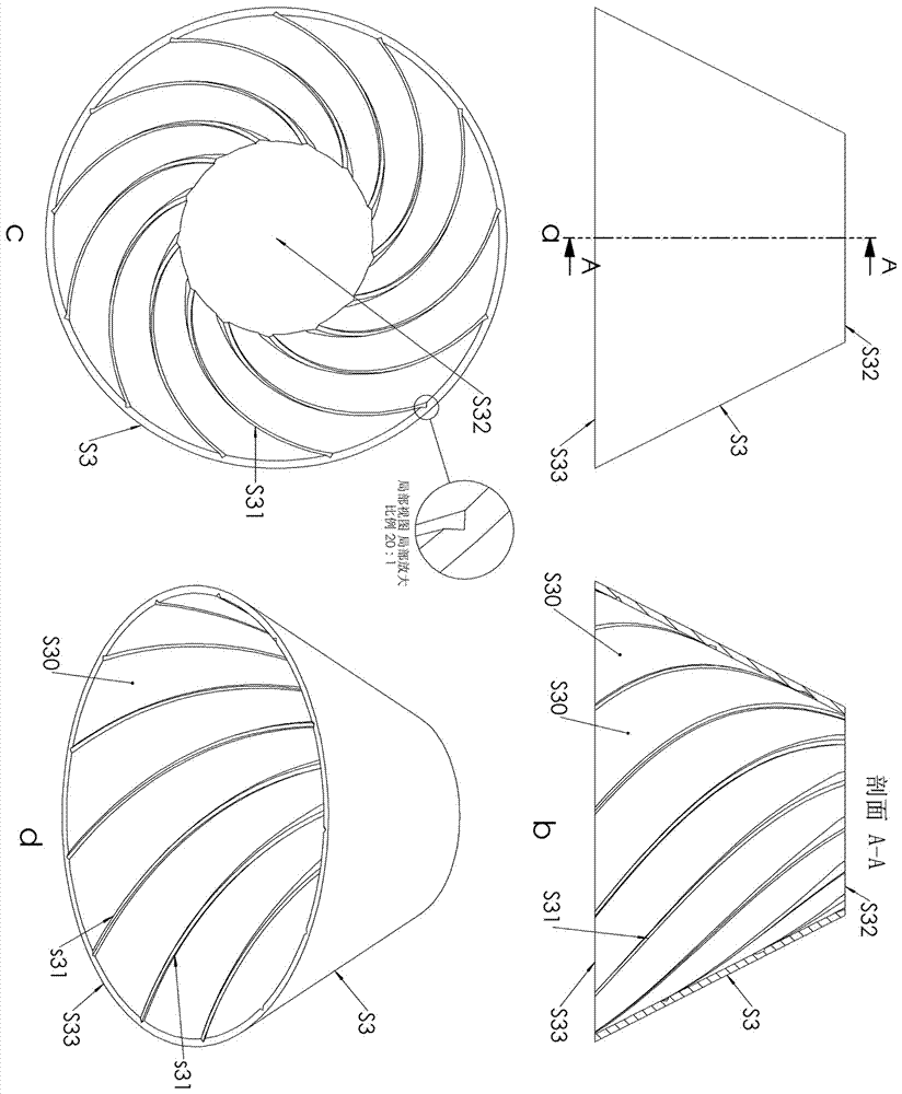
[0054] Implement Example 3, such as image 3 As shown, the fluid booster structure, S3 is the body of the one-way valve fluid booster structure, S30 is the conical cavity, S31 is the spiral guide structure, and S32 is the small end of the conical cavity, which is the one-way valve fluid booster structure S33 is the large end of the tapered cavity, which is the fluid inlet of the fluid booster structure of the one-way valve; the spiral guide structure is a spiral groove, the number of spiral plates is 12, and the spiral groove is located in a V-shaped groove.


PUM


Abstract

The invention discloses a one-way valve fluid reinforcement structure. The fluid reinforcement structure comprises a current collector, the current collector is provided with a conical cavity, the large end of which an opening is large of the conical cavity is used for inputting fluid, the small end of which an opening is small of the conical cavity is used for outputting the fluid to a valve core, and at least two spiral diversion structures which are uniformly distributed with the axial line of the conical cavity being the circumference and are of an identical structure and in the identical rotary clockwise direction are arranged at the inner wall of the conical cavity; the rotaty degree of the spiral fluid guide structures is smaller than or equal to 135 degrees; a connecting object in the connecting path between the spiral diversion structures does not penetrate through the axial line of the conical cavity in the space path, that is, in terms of the fluid, the path of the axial line of the conical cavity is straight without obstacles. The invention further discloses a one-way valve, the one-way valve with the one-way valve fluid reinforcement structure, a mosquito killing lamp or an intelligent mosquito killing lamp or an artificial intelligent mosquito killing lamp or the one-way fluid reinforcement structure or the one-way valve with the mosquito killing lamp or the intelligent mosquito killing lamp or the artificial intelligent mosquito killing lamp. The one-way valve fluid reinforcement structure is simple, long in service life and low in cost.

Description

technical field [0001] The invention relates to a fluid structure, which has a fluid booster structure, a one-way valve, an intelligent mosquito-killing device, a blower fan, a fluid-powered aircraft or a rocket, or a propeller for a ship or a submarine. technical background [0002] Flying insect killing equipment is a tool used to kill flying insects, such as moth killing lamps, mosquito killing lamps, electric mosquito swatters, etc. [0003] Utilizing wind force to suck flying insects is an important way of killing flying insects, such as mosquito killing equipment and carbon dioxide bait mosquito-absorbing equipment. [0004] When researching flying insect killing equipment, our company designed a flying insect trapping and killing equipment (see our company's patent applications No. 2017108372608 and 2017211880165), which uses detection devices (such as cameras) to monitor whether there are flying insects around the equipment. If there are flying insects, start the fa...

Claims


Application Information

Patent Timeline
Patent Type & Authority Applications(China)
IPC IPC(8): A01M1/08A01M1/02H04L29/08H04N7/18G05D13/62F16K15/02
CPCA01M1/026A01M1/08H04L67/10H04L67/12H04N7/183G05D13/62F16K15/02A01M2200/012
Inventor 刘伟
Owner HUNAN QINGCHUANG SCI & TECH CO LTD
Why Eureka
Try Eureka