
Construction method of protective layer on surface of wind turbine blade mold

A wind turbine blade and construction method technology, applied in the manufacturing field, can solve the problems of film damage, easily damaged butt joints, damage, etc., and achieve the effects of product quality assurance, reduction of peeling load, and convenient recycling.

Active Publication Date: 2017-12-15
SINOMATECH WIND POWER BLADE
View PDF6 Cites 1 Cited by
  • Summary
  • Abstract
  • Description
  • Claims
  • Application Information

AI Technical Summary

Problems solved by technology

However, this method has several problems: 1) The speed of film application is slow and requires a large number of workers to cooperate; 2) The film forms a large number of horizontal butt joints, which are inconsistent with the demoulding direction of the blade, and it is very easy to be damaged in later use; 3) Because the peeling force on the surface formed when the blade is demolded is along the direction of the blade root-tip, the butt joint of the circumferential film is basically perpendicular to the direction of the peeling force, and the peeling force is easy to damage the butt joint, and the butt joint must be used Tape or coating protection, otherwise it is easy to be taken up when demoulding, the film will be damaged, and the service life will be greatly reduced

Method used


Image

  • Construction method of protective layer on surface of wind turbine blade mold
  • Construction method of protective layer on surface of wind turbine blade mold
  • Construction method of protective layer on surface of wind turbine blade mold

Examples


Embodiment Construction

[0033] The technical solutions provided by the present invention will be described in detail below through specific embodiments of the present invention in conjunction with the accompanying drawings, so that those skilled in the art can have a clearer understanding of the present invention. It should be noted that the technical solutions provided in the following embodiments and the drawings in the description are only used to illustrate the present invention, and are not used to limit the present invention. The same elements and steps will be described with the same reference signs. In the following embodiments and drawings, components and steps not directly related to the present invention are omitted and not shown; and the dimensional relationship among the components in the drawings is only for easy understanding, not for limiting the actual ratio.

[0034] The present invention provides a method for constructing a protective layer on the surface of a wind turbine blade mo...


PUM

PropertyMeasurementUnit
Thicknessaaaaaaaaaa

Abstract

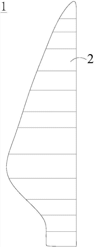
The invention provides a construction method of a protective layer on the surface of a wind turbine blade mold. The construction method comprises the steps of preparing protective tapes, wherein the outer surfaces of the protective tapes are made of low-surface energy materials, the inner surfaces of the protective tapes are made of pressure sensitive adhesives, and enhancement layers are arranged in the protective tapes; attaching a plurality of the protective tapes to the inner surface of the wind turbine blade mold in parallel, wherein the longitudinal direction of the wind turbine blade mold is from the blade root to the blade tip, the protective tapes are attached in the longitudinal direction or in a direction having a first angle relative to the longitudinal direction, and the adjacent protective tapes are butted at zero distance so as to form the protective layer with low surface energy. The invention further provides an improvement method of the method. The improvement method comprises the steps of attaching the tapes with the enhancement layers and the pressure sensitive adhesive layers to the surface of the mold first, covering the whole surface of the mold, and then integrally spraying low-surface energy paint. By adopting the method, the protective layer on the surface of the mold is difficult to damage, the protective layer can be integrally removed from the mold when reaching the service life, marks cannot be left on the surface of the mold, the recycling is convenient, and the product quality can be effectively guaranteed.

Description

technical field [0001] The invention belongs to the field of manufacturing industry, and in particular relates to a method for constructing a protective layer on the surface of a mold of a wind power blade. Background technique [0002] In the manufacturing process of wind power blades, the surface quality of wind power blade molds is very important. On the one hand, it determines the aerodynamic shape of the blades produced, which directly affects the product quality; on the other hand, it also determines the life of the molds used. In actual production, since epoxy resin, polyester resin or other high-viscosity resins are used to produce wind turbine blades, the surface of the mold needs to be repeatedly coated with a release agent to ensure that the epoxy resin does not stick to the mold and prevent damage to the mold surface . But despite the use of mold release agents for protection, the mold surface is still very vulnerable to damage. After producing several blades, ...

Claims


Application Information

Patent Timeline
IPC IPC(8): B29C33/38
Inventor 贾智源关晓方
Owner SINOMATECH WIND POWER BLADE
Learn More