
Plastic pad stamping molding device for plastic pads with rough surfaces

A stamping forming, rough surface technology, applied in the field of plastic product production equipment, can solve the problems of uneven quality, rough surface, low quality, etc., and achieve the effect of low cooling cost, uniform finished product quality, and high stamping quality

Pending Publication Date: 2017-12-15
湖州硕能纺织科技有限公司
View PDF5 Cites 1 Cited by
  • Summary
  • Abstract
  • Description
  • Claims
  • Application Information

AI Technical Summary

Problems solved by technology

[0004] The purpose of the present invention is to provide a plastic pad stamping and forming device with a rough surface, which has the advantages of more uniform surface anti-skid treatment in the production process of the plastic pad and higher quality of the finished plastic pad, and solves the problems in the production of the existing plastic pad. Issues with variable and generally low quality

Method used


Image

  • Plastic pad stamping molding device for plastic pads with rough surfaces
  • Plastic pad stamping molding device for plastic pads with rough surfaces
  • Plastic pad stamping molding device for plastic pads with rough surfaces

Examples


Embodiment Construction

[0020] The technical solutions in the embodiments of the present invention will be clearly and completely described below in conjunction with the accompanying drawings in the embodiments of the present invention. Obviously, the described embodiments are only a part of the embodiments of the present invention, rather than all the embodiments. Based on the embodiments of the present invention, all other embodiments obtained by those of ordinary skill in the art without creative work shall fall within the protection scope of the present invention.

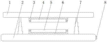
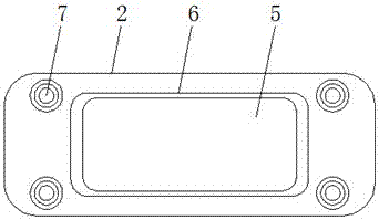
[0021] See Figure 1 to 5 , The present invention provides an embodiment: a rough-surfaced plastic pad stamping and forming device, comprising an upper frame 1, a lower base 2, an upper mold base 3, an upper mold plate 4, a lower mold plate 5, a lower mold base 6 and hydraulic The telescopic rod 7, the lower mold seat 6 is fixed at the middle position of the lower base 2, the bottom four corners of the lower mold seat 6 are concave, the ...


PUM


Abstract

The invention discloses a plastic pad stamping molding device for plastic pads with rough surfaces. The plastic pad stamping molding device comprises an upper rack, a lower base, an upper mold base, an upper mold plate, a lower mold plate, a lower mold base and a hydraulic telescopic rod. The lower mold base is fixedly arranged in the middle of the lower base. The lower mold plate is fixedly arranged in the lower mold base. Two partitions are mounted in the lower mold plate. A first cooling pipe is mounted between one of the partitions and the lower mold plate, and a second cooling pipe is mounted between the other partition and the lower mold plate. Protruding blocks are uniformly arranged in the portion, corresponding to the portion between the two partitions, of the bottom end face of the lower mold plate in a protruding manner. The hydraulic telescopic rod is mounted between the upper rack and the lower base. The top end of the hydraulic telescopic rod is fixed to the bottom face of the upper rack. The bottom end of the hydraulic telescopic rod is fixed to the upper end face of the lower base. The upper mold base is fixedly arranged in the middle position of the bottom end face of the upper rack. The upper mold plate is fixedly arranged in the upper mold base. Concave blocks matched with the protruding blocks are uniformly arranged in the upper mold plate. According to the plastic pad stamping molding device for the plastic pads with the rough surfaces, the anti-sliding plastic pads are produced by the adoption of the stamping manner, the quality of the finished plastic pads is higher, and the production quality is more uniform.

Description

Technical field [0001] The invention relates to the technical field of plastic product production equipment, in particular to a stamping and forming device for a plastic pad with a rough surface. Background technique [0002] Plastic mat is one of the common plastic products, and the plastic mat is mainly used in the field of home anti-skid. [0003] The production of plastic mats is generally made by inverting heated plastic liquid in a template to cool down. As far as the anti-slip of the plastic mat is concerned, the existing method is to make anti-slip grooves or convex grooves on the surface of the plastic mat, but the existing method is due to the template Defects in accuracy often result in uneven surface of the plastic mat, and the quality of the produced plastic mat is uneven, and the quality is generally poor. Summary of the invention [0004] The purpose of the present invention is to provide a plastic pad stamping and forming device with a rough surface, which has the a...

Claims


Application Information

Patent Timeline
IPC IPC(8): B29C43/36B29C43/52B29C43/02B29C44/02
CPCB29C43/021B29C43/36B29C43/52B29C44/02B29C2043/025
Inventor 尉本奇
Owner 湖州硕能纺织科技有限公司
Learn More