Transporting vehicle for transmission shaft

A transport vehicle and transmission shaft technology, which is applied in the directions of motor vehicles, transportation and packaging, multi-axle trolleys, etc., to achieve the effect of convenient movement, convenient use and large carrying capacity

Inactive Publication Date: 2017-12-15
HENAN XINZHOU TRANSMISSION MACHINERY CO LTD
View PDF0 Cites 1 Cited by
  • Summary
  • Abstract
  • Description
  • Claims
  • Application Information

AI Technical Summary

Problems solved by technology

[0003] The purpose of the present invention is to overcome the problems encountered by the existing drive shaft processing plants when they need to be transported from one process to the next process in the process of drive shaft processing, so as to provide a simple structure, convenient use, large carrying capacity, and convenient A drive shaft transport vehicle for the drive shaft to move in the factory area

Method used


Image

  • Transporting vehicle for transmission shaft
  • Transporting vehicle for transmission shaft
  • Transporting vehicle for transmission shaft

Examples


Embodiment Construction

[0019] The specific embodiments of the present invention will be further described below in conjunction with the accompanying drawings.

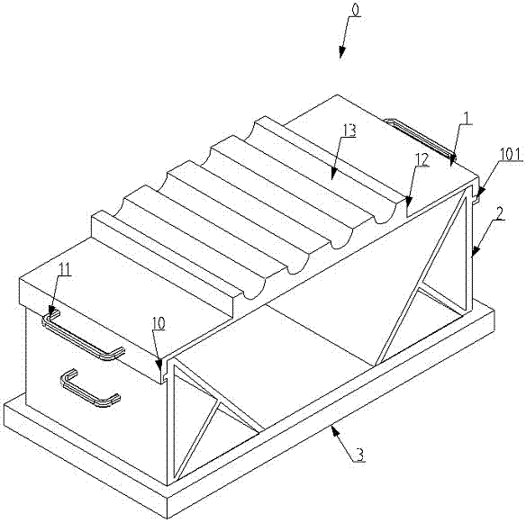
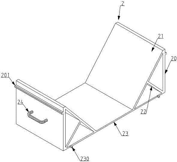
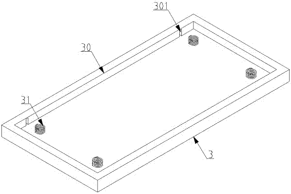
[0020] Such as figure 1 , figure 2 , image 3 As shown, a drive shaft transporter includes a transporter body 0, a base 3 is provided at the lower end of the transporter body 0, a roller is provided at the lower end of the base 3, a car body 2 is provided at the upper end of the base 3, and the car body 2 is left and right Both ends are provided with support vertical plates 20, and the lower end of the support vertical plates 20 is provided with a bottom plate 23, and an inclined support plate 21 is welded between the top of the inner surface of each support vertical plate 20 and the upper surface of the bottom plate 23. , the middle part of the inner side wall of the support plate 21 is welded with a reinforcing plate 22 at the angle between the bottom plate 23 and the vertical plate 20, and the outer end of the middle part of the suppor...


PUM


Abstract

The invention relates to a transmission shaft transport vehicle. The lower end of the transport vehicle body is provided with a base, and the lower end of the base is provided with rollers. There are clamping plates on the left and right side walls of the body bottom plate. The car body is fixedly connected by clamping into the card slots on the base. The card slots are located on the two side walls of the square groove set on the base. Compression spring, the upper connecting plate is located at the upper end of the supporting vertical plate, and the upper connecting plate is fixedly connected with the vehicle body through the cooperation of the chute and the sliding column. The top of the board is provided with a transmission shaft placement block, and the placement block is provided with a semicircular groove; generally speaking, the present invention has the advantages of simple structure, convenient use, large load capacity, and convenient movement of the transmission shaft in the factory area.

Description

technical field [0001] The invention relates to the technical field of transmission shaft transportation, in particular to a transmission shaft transportation vehicle. Background technique [0002] The transmission shaft is a rotating body with high speed and few supports, and the transmission shaft needs to go through many processes in the process of processing. Sometimes the transmission shaft needs to be transported a long way before the next process can be carried out after one process is processed. The existing transmission shaft processing plant In the process of transporting the transmission shaft, it is mostly transported by manpower, and an ordinary transmission shaft is very heavy, and it takes a lot of manpower to complete the transport; A transmission shaft transport vehicle that is large and convenient for the transmission shaft to move in the factory area has important application significance. Contents of the invention [0003] The purpose of the present in...

Claims


Application Information

Patent Timeline
Patent Type & Authority Applications(China)
IPC IPC(8): B62B3/10B62B5/00G08B5/38
CPCB62B3/102B62B5/0006B62B2203/60G08B5/38
Inventor 尚亚民
Owner HENAN XINZHOU TRANSMISSION MACHINERY CO LTD
Why Eureka
Try Eureka