
Photoelectric pod for unmanned aerial vehicle

A technology of photoelectric pods and drones, applied in the field of pods, can solve the problems of lack of vibration isolation devices, inability to rotate relative to each other, inconvenient disassembly, etc.

Inactive Publication Date: 2017-12-15
湖南翼航无人机科技有限公司
View PDF6 Cites 5 Cited by
  • Summary
  • Abstract
  • Description
  • Claims
  • Application Information

AI Technical Summary

Problems solved by technology

[0004] Most of the existing photoelectric pod shells and internal fixing frames for unmanned aerial vehicles are designed in one piece, which is inconvenient to disassemble, and there is a lack of vibration isolation devices on the internal fixing frames, resulting in strong airflow when the body shakes, The use of photoelectric components in the pod is blocked, and the shell of the pod and the pylon cannot be rotated relative to each other, resulting in limited photoelectric components for shooting or reconnaissance

Method used


Image

  • Photoelectric pod for unmanned aerial vehicle
  • Photoelectric pod for unmanned aerial vehicle
  • Photoelectric pod for unmanned aerial vehicle

Examples


Embodiment Construction

[0023] The technical solutions in the embodiments of the present invention will be clearly and completely described below in conjunction with the accompanying drawings in the embodiments of the present invention. Obviously, the described embodiments are only a part of the embodiments of the present invention, rather than all the embodiments.

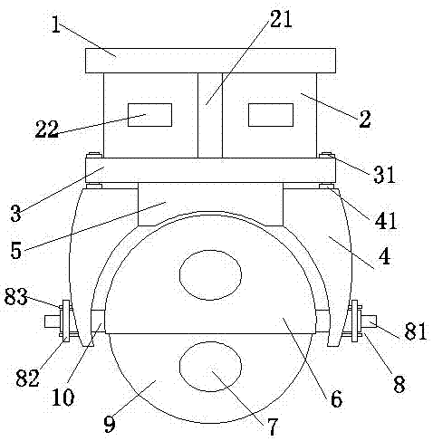
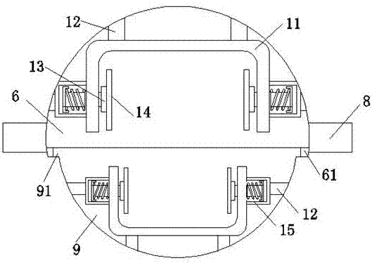
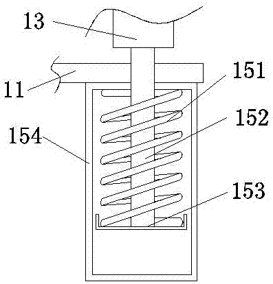
[0024] Reference Figure 1-5 , A photoelectric pod for drones, including an upper flange plate 1, a plurality of bolt holes 32 are opened on the outer edge of the upper flange plate 1 and evenly spaced along its circumference, and the bottom surface of the upper flange plate 1 passes The pylon 2 is connected with the lower flange 3, and the upper flange 1 and the lower flange 3 are arranged in parallel. The pylon 2 is a hollow structure. The side wall of the pylon 2 is evenly spaced along its circumference. A plurality of rectangular holes 22 are provided with reinforcing ribs 21 between the rectangular holes 22. The upper and lower ends of...


PUM


Abstract

The invention relates to the technical field of pods, in particular to a photoelectric pod for an unmanned aerial vehicle. The photoelectric pod comprises an upper flange plate; the bottom face of the upper flange plate is connected with a lower flange plate through a suspension frame; a mounting seat is fixed to the bottom face of the lower flange plate; lug pieces are fixed to the two ends of the mounting seat correspondingly; an upper pod body is arranged between the two lug pieces; the two ends of the upper pod body are rotatably connected with the two lug pieces through rotating shafts correspondingly; the lower end of the upper pod body is movably connected with a lower pod body; oval holes are formed in the upper pod body and the lower pod body correspondingly, and transparent glass pieces are inlaid in the oval holes; U-shaped fixed frames are fixed to the inner walls of the upper pod body and the lower pod body through supporting plates correspondingly; fixed plates are arranged on the inner sides of the two ends of each U-shaped fixed frame correspondingly; a plurality of bolt holes are formed in the outer edge of each fixed plate; and the fixed plates are connected with vibration isolation devices through connecting plates. The problems that a photoelectric pod shell for an existing unmanned aerial vehicle is inconvenient to detach, fixed frames are not provided with vibration isolation devices, the pod shell and a suspension frame cannot rotate relatively are solved.

Description

Technical field [0001] The invention relates to the technical field of pods, in particular to a photoelectric pod for drones. Background technique [0002] Unmanned aircraft is abbreviated as "unmanned aerial vehicle", which is an unmanned aircraft operated by radio remote control equipment and self-provided program control devices. There is no cockpit on board, but equipment such as autopilot and program control devices are installed. The personnel on the ground, on the ship or the remote control station of the mother aircraft use radar and other equipment to track, locate, remotely control, remotely measure and digitally transmit it. It can take off like an ordinary airplane under radio remote control or launch with a booster rocket, or it can be carried into the air by a parent plane for flight. When recovering, it can be automatically landed in the same way as an ordinary aircraft landing process, or it can be recovered by remote control using a parachute or block. Can be ...

Claims


Application Information

Patent Timeline
IPC IPC(8): B64D47/00
CPCB64D47/00B64U10/00
Inventor 李超群
Owner 湖南翼航无人机科技有限公司
Learn More