Waste lubricating oil regeneration device and regeneration technology thereof

A technology of waste lubricating oil and regeneration device, which is applied in the direction of lubricating oil distillation, petroleum industry, lubricating composition, etc., can solve the problems of high heat and electric energy consumption rate, low recovery rate, etc., and achieve the effect of heat energy reduction

Inactive Publication Date: 2017-12-15
苏州中吴能源科技股份有限公司
View PDF4 Cites 1 Cited by
  • Summary
  • Abstract
  • Description
  • Claims
  • Application Information

AI Technical Summary

Problems solved by technology

Although this document can realize the recovery of waste lubricating oil, the recovery rate

Method used


Image

  • Waste lubricating oil regeneration device and regeneration technology thereof

Examples


Embodiment 1

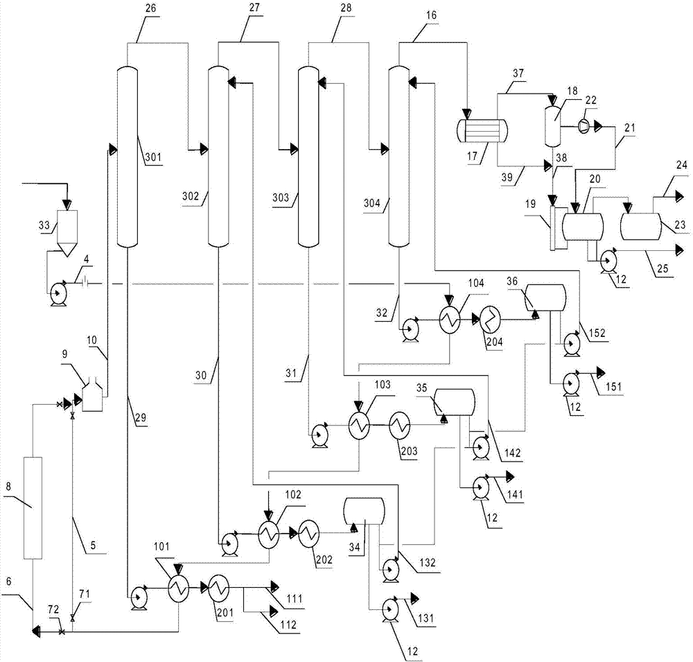
[0032] See attached figure 1 As shown, in the waste lubricating oil regeneration device in this embodiment, the pipeline 4 that enters the waste lubricating oil is sequentially connected to the inlets of 11 waste lubricating oil intermediate tanks 33, and the discharge of the last waste lubricating oil intermediate tank 33 The port is connected to the feed end of the pipeline 4, and the discharge end of the pipeline 4 containing waste lubricating oil is connected to the fourth-stage heat exchanger 104, the third-stage heat exchanger 103, the second-stage heat exchanger 102, and The inlet of the shell side of the primary heat exchanger 101 is connected in series, and the outlet of the shell side of the primary heat exchanger 101 is connected to the lubricating oil heating furnace through two parallel pipelines 5 and 6, one of which is pipeline 5 There are 1# solenoid valves 71 at both ends, the other pipeline 6 is connected in series with a preliminary distillation tower 8, and ...

Embodiment 2

[0049] As the second embodiment of the present invention, the equipment and process flow adopted are the same as those of embodiment 1. The trays of the first-stage distillation tower 301, the second-stage distillation tower 302, the third-stage distillation tower 303, and the fourth-stage distillation tower 304 The number is 18, the feed line 10 of the primary distillation column 301 is connected to the 11th tray of the primary distillation column 301, and the feed line 26 of the secondary distillation column 302 is connected to the second The twelfth tray of the three-stage distillation tower 302 is connected, and the feed line 27 of the three-stage distillation tower 303 is connected to the thirteenth tray of the three-stage distillation tower 303. The feed of the four-stage distillation tower 304 is The line 28 is connected to the 15th tray of the four-stage distillation column 304, and the line 132 at the reflux inlet of the two-stage distillation column 302 is connected to...

Embodiment 3

[0053] As the third embodiment of the present invention, the equipment and process flow adopted are the same as those of embodiment 1. The trays of the first-stage distillation tower 301, the second-stage distillation tower 302, the third-stage distillation tower 303, and the fourth-stage distillation tower 304 The number is 18, the feed line 10 of the first stage distillation column 301 is connected to the tenth tray of the first stage distillation column 301, and the feed line 26 of the second stage distillation column 302 is connected to the second The 13th plate of the three-stage distillation column 302 is connected, and the feed line 27 of the three-stage distillation column 303 is connected to the 13th plate of the three-stage distillation column 303. The feed of the four-stage distillation column 304 is The line 28 is connected to the 15th tray of the four-stage distillation column 304, and the line 132 at the reflux inlet of the two-stage distillation column 302 is conn...


PUM


Abstract

The invention discloses a waste lubricating oil regeneration device and a regeneration technology thereof. The waste lubricating oil regeneration device comprises at least one heat exchanger, at least one cooler, a lubricating oil heating furnace and at least one distilling tower, wherein a pipeline containing waste lubricating oil is connected with an inlet of a shell pass of the heat exchanger; a pipeline is arranged at an outlet of the shell pass of the heat exchanger and is connected with a material inlet at the middle lower part of the lubricating oil heating furnace; a pipeline is arranged at a material outlet of the lubricating oil heating furnace and is connected with the middle upper part of the distilling tower; a pipeline is arranged on a tower kettle of the distilling tower and is connected with an inlet of a tube pass of the cooler; a finished lubricating oil pipeline and a pipeline for communicating with the waste lubricating oil pipeline are arranged at an outlet of the tube pass of the cooler. The waste lubricating oil regeneration device has the advantages that the to-be-treated waste lubricating oil in the pipeline exchanges heat with the raw material which does not enter the treatment process by the heat exchanger, so that the consumption of heat energy is reduced; the waste lubricating oil is heated to the required temperature by the lubricating oil heating furnace, and then is sent into the distilling tower, and multiple types of lubricating oil are separated out according to different fractions, so that the recycling rate is high.

Description

Technical field [0001] The invention relates to the field of lubricant production equipment, in particular to a waste lubricant regeneration device and a regeneration process thereof. Background technique [0002] Lubricating oil is a liquid lubricant used on all kinds of machinery to reduce friction and protect machinery and processed parts. It mainly plays the role of lubrication, cooling, rust prevention, cleaning, sealing and buffering. Over time, these lubricating oils widely used in vehicles, ships, and machinery will be contaminated by air, water, dust, miscellaneous oil, and metal impurities generated by the wear of mechanical parts, and even deteriorate. Continued use can cause mechanical failure. Therefore, the lubricant must be replaced in time. [0003] Waste lubricating oil has the dual characteristics of pollution and resources: improper handling will cause serious environmental pollution, but reasonable recycling can become a valuable resource. On the one hand, man...

Claims


Application Information

Patent Timeline
IPC IPC(8): C10M175/00C10G7/00C10G7/02
CPCC10G7/003C10G7/02C10M175/00C10M175/0033C10M175/0075
Inventor 李宝亮叶兵
Owner 苏州中吴能源科技股份有限公司
Why Eureka
Try Eureka