Supercharge Your Innovation With Domain-Expert AI Agents!

A workpiece same potential temperature measuring device in a plasma vacuum coating chamber

A technology of vacuum coating and temperature measuring device, which is applied in vacuum evaporation coating, ion implantation coating, sputtering coating, etc., can solve the problems of uneven temperature distribution of plasma and surrounding environment, and can not accurately reflect the actual temperature of workpiece.

Active Publication Date: 2020-04-03
FOSHAN NANHAI JINGDINGTAI MACHINERY EQUIP CO LTD
View PDF4 Cites 0 Cited by
  • Summary
  • Abstract
  • Description
  • Claims
  • Application Information

AI Technical Summary

Problems solved by technology

[0002] As we all know, the accuracy of workpiece temperature measurement in plasma plays an important role in the process of tool plating, because the workpiece is usually in motion during the vacuum plating process, and a negative bias ranging from tens of volts to hundreds of volts is added. pressure, so there are many requirements for insulation, sealing, transmission, etc. The different positions of the heaters in the vacuum chamber have different effects on the regional temperature. The temperature distribution of the plasma and the surrounding area during the coating process is also uneven. The temperature measurement only measures the space temperature at a fixed position, and cannot accurately reflect the actual temperature of the workpiece. The workpiece material plated by the tool is very sensitive to temperature, so it is very important to master the real temperature of the actual workpiece material for the adjustment of the coating process.

Method used


Image

  • A workpiece same potential temperature measuring device in a plasma vacuum coating chamber

Examples


Embodiment Construction

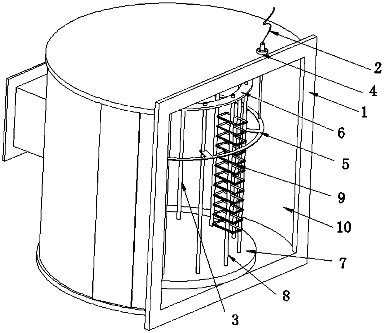
[0013] Such as figure 1 As shown, a workpiece same potential temperature measuring device in a plasma vacuum coating chamber includes a coating chamber tank body 1 and a temperature measuring thermocouple 2; a coating chamber cavity 10 is formed inside the coating chamber tank body 1; There are a workpiece rack 3 and a turntable, the workpiece rack 3 is fixed on the turntable 7, and can rotate synchronously with the turntable; the tank body 1 of the coating chamber is provided with an opening 4; Stretch into the coating chamber cavity 2 through the opening 4; the coating chamber cavity 10 is also provided with an annular heat conducting plate 5 horizontally arranged along the circumferential direction of the workpiece holder 3; the annular heat conducting plate 5 is also fixed on the workpiece holder 3 and can be The turntable rotates synchronously; the measuring end of the temperature measuring thermocouple 2 is in contact with the annular heat conducting plate 5; the outer c...


PUM


Abstract

The invention discloses an equipotential workpiece temperature measurement device for a plasma vacuum coating chamber. The equipotential workpiece temperature measurement device for the plasma vacuum coating chamber comprises a coating chamber tank and a temperature measurement thermocouple, wherein a coating chamber cavity is formed in the coating chamber tank; a workpiece rack and a rotary table are arranged in the coating chamber cavity, and the workpiece rack is fixed to the rotary table; a hole is formed in the coating chamber tank; and the measurement end of the temperature measurement thermocouple penetrates through the hole to stretch into the coating chamber cavity from the outside of the coating chamber tank. The equipotential workpiece temperature measurement device for the plasma vacuum coating chamber is characterized in that an annular heat-conducting plate which is kept synchronous with the workpiece rack and rotates horizontally is further arranged in the coating chamber cavity, the annular heat-conducting plate is fixed to the workpiece rack, and the measurement end of the temperature measurement thermocouple makes contact with the annular heat-conducting plate. By adoption of the equipotential workpiece temperature measurement device for the plasma vacuum coating chamber has the advantages that the actual potential temperature of a measured workpiece can be measured more conveniently, the technique debugging time is shortened, the production efficiency is improved, and the cost is reduced.

Description

technical field [0001] The invention relates to an on-line temperature measuring device, in particular to a workpiece same-potential temperature measuring device in a plasma vacuum coating chamber. Background technique [0002] As we all know, the accuracy of workpiece temperature measurement in plasma plays an important role in the process of tool plating, because the workpiece is usually in motion during the vacuum plating process, and a negative bias ranging from tens of volts to hundreds of volts is added. pressure, so there are many requirements for insulation, sealing, transmission, etc. The different positions of the heaters in the vacuum chamber have different effects on the regional temperature. The temperature distribution of the plasma and the surrounding area during the coating process is also uneven. The temperature measurement of the tool only measures the space temperature at a fixed position, and cannot accurately reflect the actual temperature of the workpie...

Claims


Application Information

Patent Timeline
Patent Type & Authority Patents(China)
IPC IPC(8): C23C14/54
CPCC23C14/54
Inventor 应世强尹忠乐李术杰
Owner FOSHAN NANHAI JINGDINGTAI MACHINERY EQUIP CO LTD
Features
  • R&D
  • Intellectual Property
  • Life Sciences
  • Materials
  • Tech Scout
  • Unparalleled Data Quality
  • Higher Quality Content
  • 60% Fewer Hallucinations
Learn More