Novel connecting structure for subway tunnel and extended station and construction method of novel connecting structure

A technology for connecting structures and tunnels, applied in infrastructure engineering, tunnels, underwater structures, etc.

Inactive Publication Date: 2017-12-15
SHENYANG JIANZHU UNIVERSITY
View PDF0 Cites 5 Cited by
  • Summary
  • Abstract
  • Description
  • Claims
  • Application Information

AI Technical Summary

Problems solved by technology

[0005] In order to solve the above-mentioned existing technical problems, the present invention provides a new connection structure and construction method for a subway tunnel and an extended station. It ensures that the internal force of the segment can be effectively transmitted to the station structure, and can solve the problem of bearing capacity and deformation of the shield tunnel segment in the process of connecting the interval shield tunnel with the transfer station

Method used


Image

  • Novel connecting structure for subway tunnel and extended station and construction method of novel connecting structure
  • Novel connecting structure for subway tunnel and extended station and construction method of novel connecting structure
  • Novel connecting structure for subway tunnel and extended station and construction method of novel connecting structure

Examples


Embodiment 1

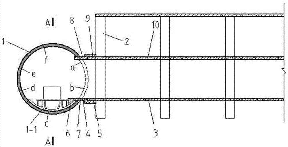
[0028] like figure 1 and 2 As shown, the present invention is a novel connecting structure between a subway tunnel and an extended station, comprising a tunnel gallery piece 1, a rail base 1-1, a load-bearing column 2, a prefabricated first bottom plate 3 on the bottom surface, a prefabricated second bottom plate 4 on the bottom surface, and a prefabricated bottom surface The third bottom plate 5, concrete leveling layer 6, waterproof material layer 7, prefabricated second bottom plate 8 on the top surface, prefabricated third bottom plate 9 on the top surface, prefabricated first bottom plate 10 and post-casting belt 11 on the top surface, special shield tunnel tube Corridor 1 is composed of 6 prefabricated standard segments a-f, and the connection sequence is clockwise from a to f, among which the standard segments a and b that are dismantled later form the opening of the platform.

Embodiment 2

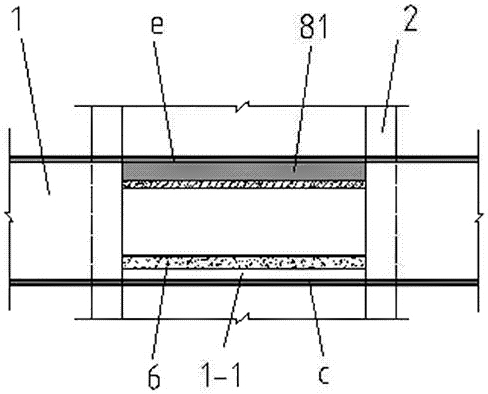
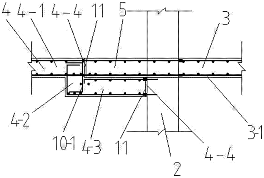
[0030] like image 3 and 5As shown, the connection between the special segment and the transfer station structure is divided into a top connection block and a bottom connection block. It consists of cast belt 11, the bottom prefabricated first base plate 3 is arranged on one side of the load-bearing column 2, the bottom prefabricated second base plate 4 and the bottom surface prefabricated third base plate 5 are arranged on the other side of the load-bearing column 2, the bottom prefabricated second floor is divided into The horizontal part 4-1, the vertical part 4-2 and the bending support part 4-3, the vertical part 4-2 and the prefabricated third base plate 5 on the bottom surface correspond to the connection gap to form a groove 4-4, and the post-casting tape is used later 11 connections.

Embodiment 3

[0032] like Figure 4 and 6 As shown, the top connecting block connection is composed of the top prefabricated first bottom plate 10, the top prefabricated second bottom plate 8, the top prefabricated third bottom plate 9 and the post-casting belt 11, and the top prefabricated first bottom plate 10 is arranged on the load-bearing column 2, the top prefabricated second bottom plate 8 and the top prefabricated third bottom plate 9 are arranged on the other side of the load-bearing column 2, and the top prefabricated second floor is divided into a horizontal part 8-1 and a vertical part 8-2 And the bending support part 8-3, the vertical part 8-2 and the prefabricated third bottom plate 9 on the top surface correspond to the connection gap to form a groove 4-4, and then use the post-casting tape 11 to grout the connection, and add a case in the grout Water-expandable waterproof glue, concrete troweling layer 6 is set at the bottom of the tunnel pipe gallery, and the height is equ...


PUM


Abstract

The invention relates to a novel connection structure between a subway tunnel and an extended station and a construction method thereof, belonging to the technical field of underground construction. Including tunnel pipe gallery, load-bearing columns, top connection block, bottom connection block, concrete plastering layer and waterproof layer, through strengthening reinforcement, it can meet the large internal force borne by the shield tunnel segment in the process of expanding the transfer station , so as to ensure the safety of the segment. By using the top connection block and the bottom connection block, the connection node has sufficient rigidity and reduces the deformation of the node. The third bottom plate is installed on the bending support of the second bottom plate, eliminating the second The settlement difference between the bottom plate and the first bottom plate makes the connection structure and force between the two very balanced, which solves the connection problem between the rigid transfer station main structure and the flexible segment structure. The shape of the special shield segment of the invention is consistent with that of the shield segment of the common subway interval tunnel, and can be produced by using the same mold as the shield segment of the ordinary subway interval tunnel.

Description

technical field [0001] The invention relates to the technical field of underground construction, in particular to a novel connection structure between a subway tunnel and an extended station and a construction method thereof. Background technique [0002] In order to speed up the construction of subways in major cities in my country, improve project quality, and ensure construction safety, shield tunneling should be used as much as possible in subway tunnels. However, due to the impact of station construction, the efficiency of shield machines has not been fully utilized. For this reason, the construction scheme of expanding the station on the basis of shield tunneling in the interval is introduced, which can well solve the contradiction between station construction and shield construction in the interval. [0003] Although the subway tunnel and the transfer station are a whole, there is a sequence for the construction of each part. When the subway tunnel is constructed in a...

Claims


Application Information

Patent Timeline
Patent Type & Authority Applications(China)
IPC IPC(8): E02D29/045E02D29/16E21D9/06
CPCE02D29/04E02D29/16E21D9/06
Inventor 张延年庚佳
Owner SHENYANG JIANZHU UNIVERSITY
Why Eureka
Try Eureka