
Eureka
For R&D, Eureka makes reading and utilizing patents & technical documents easy.
Eureka AIR
Designed for self-driven R&D workflows. Generate viable solutions, solve complex R&D challenges, empower your innovation with AI.

Eureka Materials
Designed for material experts only. Revolutionize your material R&D, from search, analyze, to developing new materials.

TechResearch
Generate reliable direction feasibility study reports for your R&D in just a few steps.

TechSeek
Discover and master advanced knowledge NOW. Basics, ideas, possibilities, all at once.

TechMind
As an expert in R&D Theories, TechMind can generates customized viable solutions instantly.

TechRisk
Analyze your overall solution with one click, know your potential R&D risks in advance.

TechMonitor
Get weekly tech updates, stay abreast of the latest tech innovations and key insights.
Exhaust manifold for a two-stage engine charge air system
A technology for exhaust manifolds and engines, which is applied in the direction of engine components, machines/engines, exhaust devices, etc., and can solve problems such as limited space
- Summary
- Abstract
- Description
- Claims
- Application Information
AI Technical Summary
Problems solved by technology
Method used
Image

Examples
Embodiment Construction
[0032] Although the present invention is capable of various modifications and alternative forms, specific embodiments have been illustrated in the drawings by way of example and described in detail below. However, it is not intended to limit the invention to the specific embodiments described. On the contrary, the present invention is intended to cover all modifications, equivalent structures, and alternatives falling within the scope of the present invention defined by the appended claims.
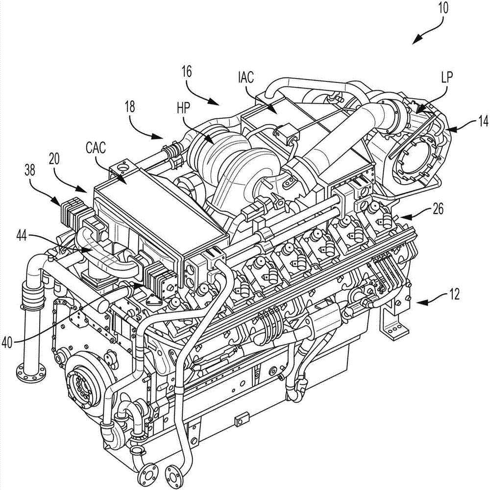
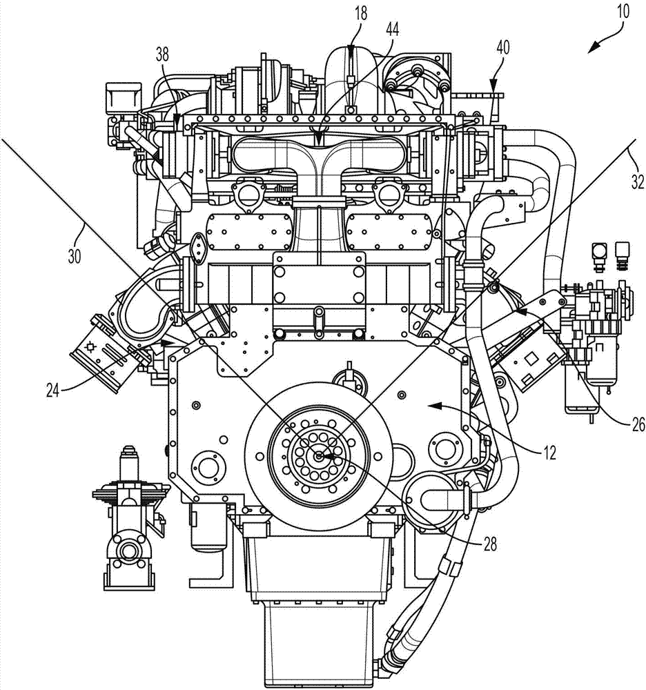
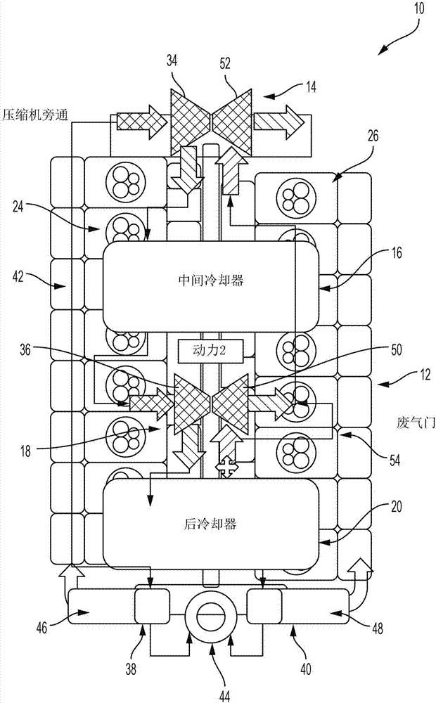
[0033] Figure 1-Figure 4 A two-stage turbocharging system according to the principles of the present disclosure is depicted. Generally, the system 10 includes a VEE-structure engine 12, a low-pressure turbocharger 14, an intermediate air cooler 16 (or intercooler 16), a high-pressure turbocharger 18, a charge air cooler 20 (or after-cooling 器20) and exhaust manifold 22 ( Figure 7A-Figure 7B ). As described in more detail below, turbochargers 14, 18, coolers 16, 20, and exhaust manifold 22...
PUM
 Abstract
Description
Claims
Application Information
 - R&D Engineer
- R&D Manager
- IP Professional
- Industry Leading Data Capabilities
- Powerful AI technology
- Patent DNA Extraction
Browse by: Latest US Patents, China's latest patents, Technical Efficacy Thesaurus, Application Domain, Technology Topic, Popular Technical Reports.
© 2024 PatSnap. All rights reserved.Legal|Privacy policy|Modern Slavery Act Transparency Statement|Sitemap|About US| Contact US: help@patsnap.com