
Wall-hanging air conditioner and protective tube support

An air conditioner and wall-mounted technology, which is applied in the field of protective pipe brackets, can solve the problems of being easily deflected by the lower base, disassembled, and the thermal insulation effect is deteriorated, so as to avoid the phenomenon of pipe cutting, facilitate disassembly and cleaning, and facilitate installation. Effect

Active Publication Date: 2017-12-15
AUX AIR CONDITIONING LTD BY SHARE LTD
View PDF5 Cites 8 Cited by
  • Summary
  • Abstract
  • Description
  • Claims
  • Application Information

AI Technical Summary

Problems solved by technology

In the process of removing the lower base, there is friction between the back of the lower base and the pipeline bundle due to relative movement. Multiple disassembly and installation of the lower base will easily cause the insulation tube around the connecting pipe to be worn out (pipe cutting phenomenon), resulting in insulation failure. The effect becomes worse, and even causes condensation on the outer wall of the connecting pipe
In addition, the pipeline bundle is a non-fixed structure with low rigidity. During the disassembly and installation of the lower base, its position is easily biased by the lower base, which increases the difficulty of installation and disassembly.
[0005] Some air conditioners in the prior art are equipped with protective devices to avoid pipe cutting when the lower base is disassembled and installed. However, when such a protective device is installed on the wall-mounted board, the lower base needs to be artificially raised to leave enough space Only then can it be realized, or even the whole machine needs to be disassembled to realize
Moreover, the protective device needs to be installed before the lower base is installed, the process is cumbersome and the reliability is not high

Method used


Image

  • Wall-hanging air conditioner and protective tube support
  • Wall-hanging air conditioner and protective tube support
  • Wall-hanging air conditioner and protective tube support

Examples


Embodiment Construction

[0036] The following will clearly and completely describe the technical solutions in the embodiments of the application with reference to the drawings in the embodiments of the application. Apparently, the described embodiments are only some of the embodiments of the application, not all of them. Based on the embodiments in this application, all other embodiments obtained by persons of ordinary skill in the art without creative efforts fall within the protection scope of this application.

[0037]Unless otherwise defined, the technical terms or scientific terms used herein shall have the usual meanings understood by those skilled in the art to which the application belongs. "First", "second" and similar words used in the specification and claims of this patent application do not indicate any sequence, quantity or importance, but are only used to distinguish different components. Likewise, words like "a" or "one" do not denote a limitation in quantity, but indicate that there i...


PUM


Abstract

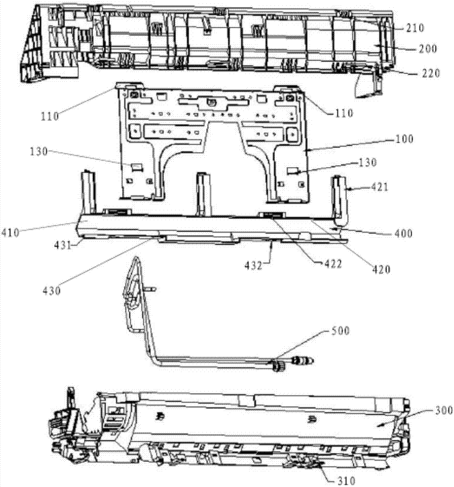
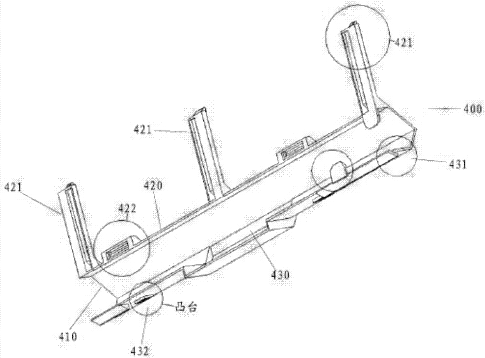
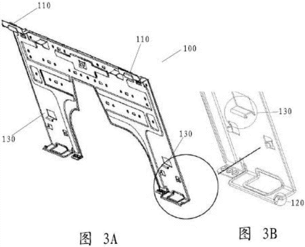
The invention relates to a wall-hanging air conditioner and a protective tube support. The wall-hanging air conditioner comprises a wall-hanging plate, an upper base, a lower base and a protective plate, wherein the wall-hanging plate is fixed on the wall during installation and has a plurality of hanging plate connecting characteristics; a heat exchanger is contained in the upper base; the upper base has a hanging characteristic and is detachably hung on at least one of the plurality of hanging plate connecting characteristics of the wall-hanging plate; an air passage component is contained in the lower base; the lower base is detachably connected to the upper base; the protective plate comprises a cavity for containing a pipeline bundle, an upper side wall and a lower side wall which extend outwards from the cavity; the protective plate, the upper base and the lower base are assembled together; and the protective plate has a compression joint characteristic so as to be in compression joint with at least one of the plurality of hanging plate connecting characteristics of the wall-hanging plate.

Description

technical field [0001] The present application relates to a wall-mounted air conditioner and a protective tube bracket for the wall-mounted air conditioner. Background technique [0002] The air duct of the air conditioner (indoor unit) is easily polluted and affects the environmental quality. In order to clean the air conditioner, an air conditioner that is easy to clean is currently being developed. For this reason, the middle frame of the air conditioner can be designed to be easily detached from the base, and the base can be split into an upper base and a lower base, so as to realize cleaning inside the air conditioner. [0003] In the process of cleaning the air conditioner, first disassemble the middle frame of the air conditioner from the upper base and the lower base, and then disassemble the lower base from the upper base, and the upper base is fixed on the wall through the wall hanging plate. In the process of cleaning the air conditioner, only the base needs to b...

Claims


Application Information

Patent Timeline
IPC IPC(8): F24F1/00F24F13/20F24F13/02
CPCF24F1/0007F24F1/0057F24F13/0254F24F13/20
Inventor 尚彬霍彪张华中古汤汤倪晓龙张坤鹏张玉忠曾友坚林益波张引
Owner AUX AIR CONDITIONING LTD BY SHARE LTD
Learn More