Inspection correction method of visual inspection device

A technology of visual detection device and correction method, which is applied in the field of visual detection, can solve the problems of inability to correct the position of materials or products, great influence on the recognition of objects, and inability to extract reference templates, etc., achieving high degree of automation, good detection effect, and high speed fast effect

Inactive Publication Date: 2017-12-15
GUANGDONG FXD INTELLIGENT EQUIP CO LTD
View PDF9 Cites 2 Cited by
  • Summary
  • Abstract
  • Description
  • Claims
  • Application Information

AI Technical Summary

Problems solved by technology

[0003] Machine vision is used more and more in the field of automation. Many software developers use machine vision libraries provided by visual processing software such as Halcon and OpenCV to perform recognition. Unfortunately, due to machine vision applications, lighting, surrounding environments, etc. The impact is very large, which makes it impossible to extract a suitable reference template, which ultimately affects the recognition effect
[0004] Existing visual inspection devices and methods are unable to correct the position of the detected materials or products, and at the same time, it is necessary to stop at the camera position for detection during detection, and problems such as low detection efficiency and low work efficiency need to be solved

Method used


Image

  • Inspection correction method of visual inspection device

Examples


Embodiment Construction

[0043] The present invention will be further described below in conjunction with the accompanying drawings.

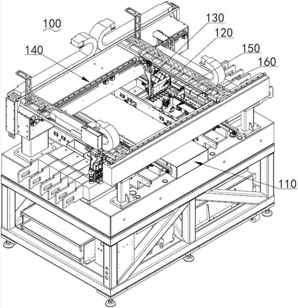
[0044] Such as figure 1 Shown is a perspective view of the visual detection device of the present invention.

[0045]A detection and correction method for a visual detection device, the visual detection device 100 includes a control system 110, a material suction module 120, a correction module 130, a transmission module 140, a detection module 150 and a fixture module 160, and the control system 110 is used to control The operation effect is to achieve the effect of absorbing and placing materials through the suction module 120, to achieve the effect of position correction through the correction module 130, to achieve the effect of driving and transmission through the transmission module 140, to achieve the effect of shooting and detecting materials through the detection module 150, and to achieve the effect of shooting and detecting materials through the jig The eff...


PUM


Abstract

The invention relates to the technical field of visual inspection, in particular to an inspection correction method of a visual inspection device. The visual inspection device comprises a control system, a suction module, a correction module, a transmission module, an inspection module and a jig module. The inspection correction method comprises steps as follows: the suction module sucks a material, the transmission module drives the suction module to move, the inspection module is used for inspecting the position of the material sucked by the suction module when the suction module moves and passes by the inspection module, the inspection module inspects the edge outline position of the material and transmits data to the control system, the control system determines whether the position of the material is accurate, the correction module corrects the position of the material when the position is not accurate, the transmission module does not stop during the period when the inspection module inspects the material and the correction module corrects the position, and the suction module places the material on the jig module. The inspection speed is high, the device does not stop in the conveying process, the working efficiency is high, and the automation degree is high.

Description

technical field [0001] The invention relates to the technical field of visual inspection, in particular to a detection and correction method of a visual inspection device. Background technique [0002] Machine vision is the use of machines instead of human eyes for measurement and judgment. The machine vision system refers to converting the target to be detected into digital signals through machine vision products (ie, image capture devices, such as CMOS and CCD), and these digital signals are then sent to dedicated image processing systems (sub-embedded and video card methods) ), the image processing system sets the detection task according to the task requirements to be detected, and then controls the on-site equipment action according to the result of the discrimination. [0003] Machine vision is used more and more in the field of automation. Many software developers use machine vision libraries provided by visual processing software such as Halcon and OpenCV to perform...

Claims


Application Information

Patent Timeline
Patent Type & Authority Applications(China)
IPC IPC(8): G01C25/00G01B11/00
CPCG01C25/00G01B11/00
Inventor 候立新
Owner GUANGDONG FXD INTELLIGENT EQUIP CO LTD
Why Eureka
Try Eureka