Supercharge Your Innovation With Domain-Expert AI Agents!

A shockproof, heat-resistant temperature sensor

A heat-resistant temperature and sensor technology, used in heat-resistant temperature sensors and shock-proof fields, can solve problems such as pull-off, temperature sensor failure, thermal conductive adhesive deformation, etc., to avoid loosening and failure.

Active Publication Date: 2020-09-01
贵阳永青智控科技股份有限公司
View PDF7 Cites 1 Cited by
  • Summary
  • Abstract
  • Description
  • Claims
  • Application Information

AI Technical Summary

Problems solved by technology

[0002] The working environment of construction machinery vehicles is relatively harsh, which causes the temperature sensor on the construction machinery vehicles to work in a compound environment of high temperature and vibration for a long time. The original temperature sensing element adopts in-line welding (the lead wire of the temperature sensing element is welded on the circuit board) , due to the need to ensure a good heat conduction effect, it is necessary to fill the inside of the temperature sensor (that is, around the temperature sensing element) with thermal conductive glue, and when the original thermometer is working, due to the different thermal conductivity and deformation of the thermal conductivity glue, the lead wires of the temperature sensing element will be damaged. The temperature sensor was pulled off, causing the temperature sensor to fail. The wire is easily damaged and loosened in harsh environments, which can no longer meet the current market demand. According to market requirements, a shockproof and heat-resistant temperature sensor with higher reliability and higher precision is designed.

Method used


Image

  • A shockproof, heat-resistant temperature sensor
  • A shockproof, heat-resistant temperature sensor

Examples


Embodiment Construction

[0017] The technical solution of the present invention is further described below, but the scope of protection is not limited to the description.

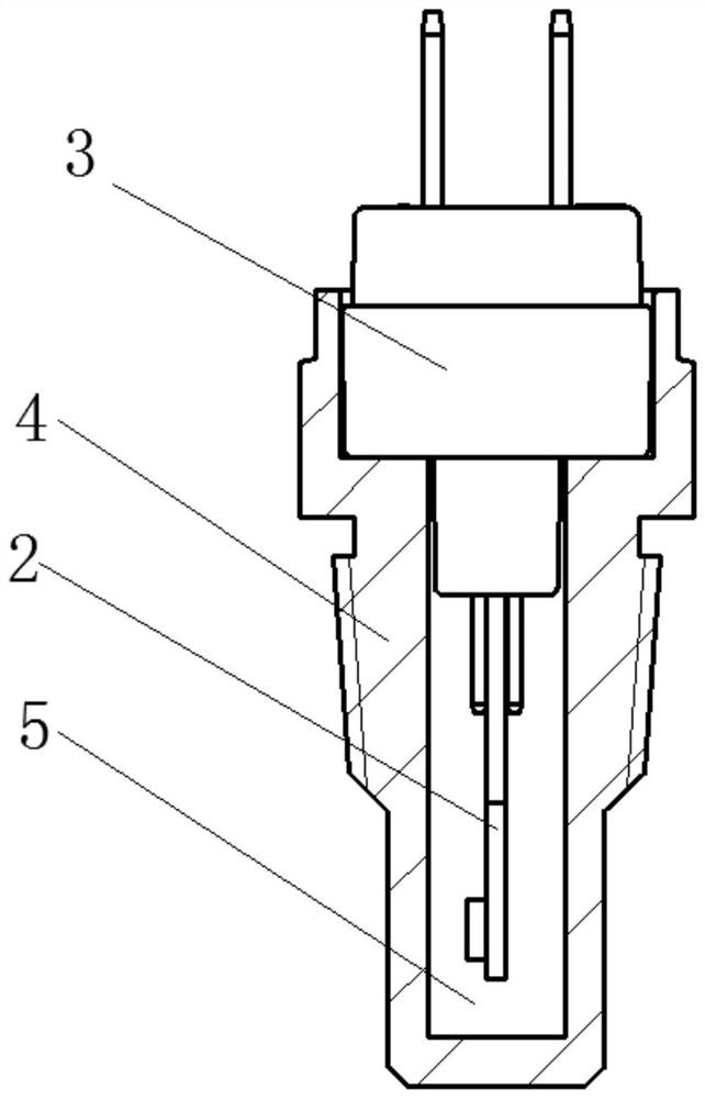
[0018] A shockproof and heat-resistant temperature sensor, comprising a detection element 1, a circuit board 2, a mounting base 3, a heat conduction cover 4, and an insertion piece 7; the two ends of the mounting base 3 are installation ends and detection ends respectively, and the detection element 1 is installed on the detection end of the mounting base 3, the insert piece 7 is installed on the mounting end of the mounting base 3, a heat conduction cover 4 is also provided on the detection end of the mounting base 3, and the detection element 1 is installed through the circuit board 2 On mount 3. By changing the connection mode of the sensor to patch connection, the loosening of the connection point is avoided, and it also prevents the heat-conducting glue from deforming after being heated when the sensor is working during the te...


PUM


Abstract

The invention provides a shockproof and heat-resistant temperature sensor, which includes a detection element, a circuit board, a mounting seat, a heat conduction cover, and an insertion piece; the two ends of the mounting seat are respectively a mounting end and a detection end, and the detection element is installed The detection end of the mounting base, the insertion piece is installed on the mounting end of the mounting base, a heat conduction cover is also arranged on the detection end of the mounting base, and the detection element is installed on the mounting base through a circuit board. In the present invention, by changing the connection mode of the sensor to a patch connection, the loosening of the connection point is avoided, and the heat-conducting glue is deformed after being heated when the sensor is working during the temperature detection process, and at the same time, it is in a vibrating environment, causing the temperature-sensing element to be disconnected. The foot wire is pulled off to avoid the failure of the temperature sensor.

Description

technical field [0001] The invention relates to a shockproof and heat-resistant temperature sensor. Background technique [0002] The working environment of construction machinery vehicles is relatively harsh, which causes the temperature sensor on the construction machinery vehicles to work in a compound environment of high temperature and vibration for a long time. The original temperature sensing element adopts in-line welding (the lead wire of the temperature sensing element is welded on the circuit board) , due to the need to ensure a good heat conduction effect, it is necessary to fill the inside of the temperature sensor (that is, around the temperature sensing element) with thermally conductive glue. When the original thermometer is working, due to the different thermal conductivity and the deformation of the thermally conductive glue, the lead wires of the temperature sensing element will be damaged. If it is pulled off, the temperature sensor will fail, and the wir...

Claims


Application Information

Patent Timeline
Patent Type & Authority Patents(China)
IPC IPC(8): G01K1/08G01K1/12G01K1/14
CPCG01K1/08G01K1/12G01K1/14
Inventor 叶兵刘朝富
Owner 贵阳永青智控科技股份有限公司
Features
  • R&D
  • Intellectual Property
  • Life Sciences
  • Materials
  • Tech Scout
  • Unparalleled Data Quality
  • Higher Quality Content
  • 60% Fewer Hallucinations
Learn More