Supercharge Your Innovation With Domain-Expert AI Agents!

Connector

一种连接器、同轴电缆的技术,应用在连接、导电连接、两部件连接装置等方向,能够解决增大紧固环4和被折叠的屏蔽部件8摩擦力、连接器1大型化、紧固环易脱落等问题

Active Publication Date: 2020-04-28
JAPAN AVIATION ELECTRONICS IND LTD
View PDF7 Cites 0 Cited by
  • Summary
  • Abstract
  • Description
  • Claims
  • Application Information

AI Technical Summary

Problems solved by technology

Therefore, there is a problem that the fastening ring 4 is easy to fall off during the work of installing the connector 1.
[0009] Moreover, if the axial length of the cylindrical portion 3A of the housing 3 and the fastening ring 4 is increased in order to suppress the fastening ring 4 from falling off, the radial direction of the coaxial cable 5 between the fastening ring 4 and the shielding member 8 and the The pressed area of ​​the sleeve 9 increases the frictional force between the fastening ring 4 and the folded shielding part 8, which causes the problem of increasing the size of the connector 1

Method used


Image

  • Connector
  • Connector
  • Connector

Examples


Embodiment Construction

[0032] Hereinafter, embodiments of the present invention will be described with reference to the drawings.

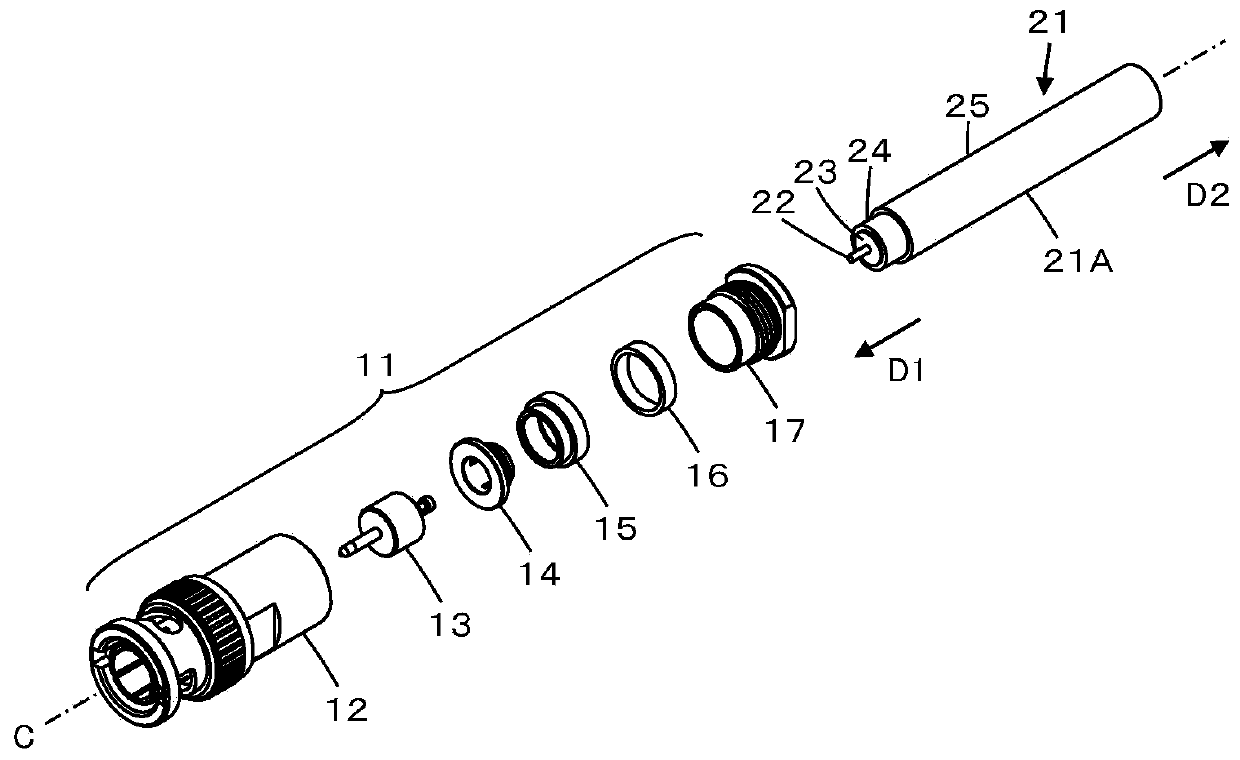
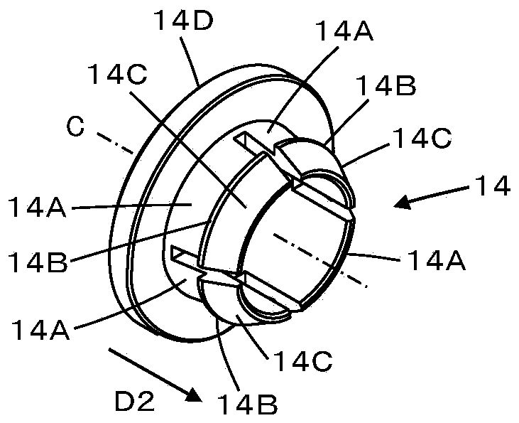
[0033] figure 1 It is an assembly drawing of the connector 11 which concerns on embodiment. The connector 11 is installed on the front end 21A of the coaxial cable 21, and has the following structure, that is, along the central axis C, the central contact assembly 13, the inner sleeve 14, and the outer sleeve are sequentially assembled in the connector body 12. 15. Washer 16 and fastening nut 17.

[0034] Furthermore, the coaxial cable 21 has a central conductor 22 , an insulator 23 covering the outer periphery of the central conductor 22 , a shield member 24 covering the outer periphery of the insulator 23 , and a sleeve 25 covering the outer periphery of the shield member 24 .

[0035] At this time, for convenience, the direction along the coaxial cable 21 and toward the front end 21A of the coaxial cable 21 is referred to as a first direction D1, and the direction...


PUM


Abstract

A connector includes an inner sleeve through which a central conductor and an insulator of a coaxial cable are passed and an outer sleeve through which the central conductor, the insulator and a shield member of the coaxial cable are passed, the inner sleeve including projection portions that are arranged in a circumferential direction, project outward in a radial direction and are inserted between the insulator and the shield member of the coaxial cable, and at least one of the projection portions is elastically displaceable in the radial direction, the outer sleeve including an inner peripheral surface that covers the projection portions and tapers in a first direction directed toward the front end of the coaxial cable along the coaxial cable, the shield member of the coaxial cable being sandwiched between the projection portions of the inner sleeve and the inner peripheral surface of the outer sleeve.

Description

technical field [0001] This invention relates to connectors, and more particularly to connectors mounted on the ends of coaxial cables. Background technique [0002] In the past, connectors have been used for the connection of coaxial cables. For example, Patent Document 1 discloses Figure 9 Connector 1 as shown. The connector 1 includes a housing 3 and a fastening ring 4 , and a coupling nut 2 is rotatably fitted in the housing 3 . Coaxial cable 5 has a structure in which the outer peripheral portion of central conductor 6 is covered with insulator 7 , and the outer peripheral portion of insulator 7 is covered with shield member 8 and sleeve 9 . [0003] When the connector 1 is installed on the coaxial cable 5, first, the coaxial cable 5 passes through the fastening ring 4, and after removing the predetermined length of the sleeve 9 at the front end of the coaxial cable 5, the shielding member 8 is folded to the same position. The outer peripheral portion of the axial ca...

Claims


Application Information

Patent Timeline
Patent Type & Authority Patents(China)
IPC IPC(8): H01R13/502H01R13/426H01R13/40H01R4/18H01R24/38H01R9/05
CPCH01R4/183H01R9/0521H01R9/0527H01R13/40H01R13/426H01R13/502H01R24/38H01R9/0524
Inventor 松本正和
Owner JAPAN AVIATION ELECTRONICS IND LTD
Features
  • R&D
  • Intellectual Property
  • Life Sciences
  • Materials
  • Tech Scout
  • Unparalleled Data Quality
  • Higher Quality Content
  • 60% Fewer Hallucinations
Learn More