Traction network hanging structure, power supply loop traction device and shield tunnel system

A technology of power supply circuit and traction device, applied in tunnels, mining equipment, mining equipment, etc., can solve the problems of inability to connect, occupy, large space, etc., and achieve the effect of simple suspension

Pending Publication Date: 2017-12-19
CHINA RAILWAY SIYUAN SURVEY & DESIGN GRP
View PDF10 Cites 1 Cited by
  • Summary
  • Abstract
  • Description
  • Claims
  • Application Information

AI Technical Summary

Problems solved by technology

[0003] On the one hand, the rear anchor bolt fixing structure adopted in the prior art cannot be connected with the pre-embedded channel. On the other hand, since the rear anchor bolt is fixed vertically at the curved position, the suspension structure needs to be adjusted by using inclined spacers. It can ensure that the traction net is flush with the rail surface, and the vertical fixing method takes up a lot of space, which further reduces the installation space of the traction net suspension structure and increases the difficulty of installation

Method used


Image

  • Traction network hanging structure, power supply loop traction device and shield tunnel system
  • Traction network hanging structure, power supply loop traction device and shield tunnel system
  • Traction network hanging structure, power supply loop traction device and shield tunnel system

Examples


Embodiment Construction

[0024] The following will clearly and completely describe the technical solutions in the embodiments of the present invention with reference to the accompanying drawings in the embodiments of the present invention. Obviously, the described embodiments are only some, not all, embodiments of the present invention. Based on the embodiments of the present invention, all other embodiments obtained by persons of ordinary skill in the art without making creative efforts belong to the protection scope of the present invention.

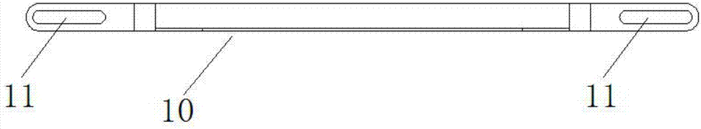
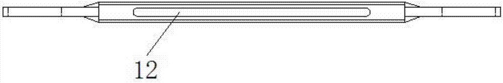
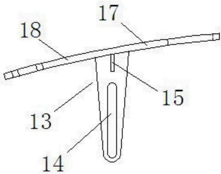
[0025] see figure 1 , image 3 and Figure 5 , the embodiment of the present invention provides a traction net suspension structure, including a first connector 10 and two second connectors 13 arranged at intervals, wherein the first connector 10 is for the traction net to be installed, and the two second connectors 13 are both There is a first elongated hole 14 extending in the vertical direction, and the suspension structure also includes two third connect...


PUM


Abstract

The invention relates to the field of urban rail transportation traction networks and provides a traction network hanging structure. The traction network hanging structure comprises a first connecting piece, two second connecting pieces and two third connecting pieces arranged at the two ends of the first connecting pieces correspondingly. According to the traction network hanging structure, the problem that in the prior art, due to limitation of a mounting space, mounting difficulty is large. The invention further provides a power supply loop traction device and a shield tunnel system. The power supply loop traction device comprises a traction network and the traction network hanging structure, wherein the traction network is hung on the traction network hanging structure. The power supply loop traction device adopts the traction network hanging structure, so that hanging of the traction network becomes easier. The shield tunnel system comprises a shield segment, a groove channel pre-embedded in the shield segment and the power supply loop traction device. The power supply loop traction device is mounted on the lower portion of the shield segment. According to the shield tunnel system, the problem that the hanging structure is difficult to mount when the discontinuous groove channel exists is solved through fixing pieces.

Description

technical field [0001] The invention relates to the field of urban rail transit traction nets, in particular to a traction net suspension structure, a power supply circuit traction device and a shield tunnel system. Background technique [0002] The diameter of the urban rail transit shield tunnel is a 5400mm circular structure, and in the case of a civil engineering error of 100mm, the maximum space in the tunnel is 5200mm. In the fixed traction network, the height of the traction network wire from the rail surface is 4040mm (that is, the pantograph height), the track bed height is 760mm. The actual space given to the suspension structure of the traction net is 5200-4040-760=400mm. [0003] On the one hand, the rear anchor bolt fixing structure adopted in the prior art cannot be connected with the pre-embedded channel. On the other hand, since the rear anchor bolt is fixed vertically at the curved position, the suspension structure needs to be adjusted by using inclined sp...

Claims


Application Information

Patent Timeline
Patent Type & Authority Applications(China)
IPC IPC(8): E21F17/06E21F17/02E21D9/06
CPCE21D9/06E21F17/02E21F17/06
Inventor 黄冬亮徐鸿燕吴江涛刘欢
Owner CHINA RAILWAY SIYUAN SURVEY & DESIGN GRP
Why Eureka
Try Eureka