Inexpensive cholera diagnosis microfluidic apparatus with tortuous liquid flow transmission route

A microfluidic device and flow transmission technology, applied in the field of analysis and testing, can solve the problems that have not been properly solved, the flow resistance is large, and the passage of fine liquid flow is difficult.

Inactive Publication Date: 2017-12-19
李榕生
View PDF1 Cites 0 Cited by
  • Summary
  • Abstract
  • Description
  • Claims
  • Application Information

AI Technical Summary

Problems solved by technology

[0007] But it's not that simple
[0008] First, this polydimethylsiloxane material, which is referred to by the acronym PDMS, is itself a strongly hydrophobic material, and channels are built on this material. modification operation, then, after the overall assembly is completed, that is, after the cover is covered, because the inner surface of the channel in the structure occupies most of the inner surface of the liquid flow channel, then the inner surface of the PDMS channel is The strong hydrophobicity is the decisive factor, it will make it very difficult for the polar liquid fine flow similar to the aqueous solution to pass through, and its flow resistance is so large that even the general micropump is difficult to push, of course, if the cover sheet is also If you choose to use the PDMS material, then the problems are basically the same, with minor differences; therefore, in the prior art, it is necessary to modify and modify the inner surface of the channel on the PDMS material; then, this is for the PDMS channel Is the modification operation of the inner surface of the channel very troublesome? That's not the problem. What constitutes a serious technical problem is an

Method used


Image

  • Inexpensive cholera diagnosis microfluidic apparatus with tortuous liquid flow transmission route

Examples


Embodiment Construction

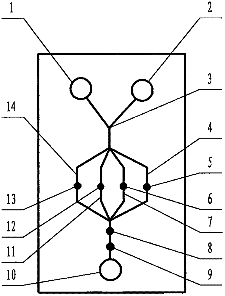
[0068] exist figure 1 In the illustrated embodiment of the present case, the structure of the microfluidic device includes a multi-channel microfluidic chip, and the structure of the microfluidic chip includes a substrate and a cover that are attached to each other and installed together. The substrate and the cover sheet are plates or sheets, the surface of the substrate facing the cover sheet contains a channel structure formed by a molding process or an etching process, and the substrate also contains a channel structure connected to the channel structure and The window structure is formed through the molding process, etching process or simple drilling process through the substrate, and the substrate and the cover are installed together to form a pipe structure and a liquid pool connected to it. The structure of the microfluidic chip, the liquid pool is the liquid pool 1, the liquid pool 2, the liquid pool 10, the structural position of the pipeline is located in the interf...


PUM

PropertyMeasurementUnit
Particle sizeaaaaaaaaaa
Diameteraaaaaaaaaa
Lengthaaaaaaaaaa

Abstract

The present invention relates to an inexpensive cholera diagnosis microfluidic apparatus with a tortuous liquid flow transmission route, and belongs to the field of analytical testing. According to the present invention, the use of inexpensive and easily-processed polydimethylsiloxane (PDMS) to produce the substrate of a microfluidic chip for cholera diagnosis has a series of problems that the surface of the PDMS is strongly hydrophobic and the surface chemical modification effect is difficult to last. The technical scheme of the present invention is that the substrate material is PDMS with an original ecological surface, the pipeline of the chip is filled with doped micron-scale titanium dioxide particles, the surface super-hydrophilicity of the titanium dioxide particles can be induced by visible light irradiation in advance, and the set of the titanium dioxide particle filler and the super-hydrophilic gap between the particles can compensate and beyond the original strong hydrophobic pipeline, such that the constant and super hydrophilic modification effect is achieved. In addition, the titanium dioxide filler can further be used for preventing the pipeline of the chip from collapsing and deforming, and blocking biological macromolecules from contacting the inner wall of the pipeline.

Description

technical field [0001] The invention relates to a low-cost microfluidic device for cholera diagnosis with tortuous liquid flow transmission route, which belongs to the field of analysis and testing. Background technique [0002] For the technical background of multi-channel microfluidic cholera diagnosis, please refer to CN 200910150930.4 and other invention patent applications. [0003] As far as the overall overview of microfluidic technology itself is concerned, you can refer to the monograph "Illustrated Microfluidic Chip Laboratory" published by the famous microfluidic expert Mr. Lin Bingcheng not long ago, which has been published by Science Press. The past, present, and future prospects of microfluidic technology, etc., have detailed and long-form discussions that go deep into specific details. [0004] So, let's talk about the key issues of this case. [0005] The basic structure of a microfluidic chip includes a substrate etched with channels and a cover sheet att...

Claims


Application Information

Patent Timeline
IPC IPC(8): G01N33/569G01N27/48
CPCG01N27/48G01N33/56911G01N2800/26Y02A50/30
Inventor 李榕生
Owner 李榕生
Why Eureka
Try Eureka