Method of realizing material locating of numerical-control cutting bed equipment

A material positioning and material technology, applied in image data processing, instruments, calculations, etc., can solve the problems of material waste, cutting work stagnation, errors, etc.

Inactive Publication Date: 2017-12-19
SHENZHEN BUYI TECH
View PDF9 Cites 7 Cited by
  • Summary
  • Abstract
  • Description
  • Claims
  • Application Information

AI Technical Summary

Problems solved by technology

[0009] However, this method has the following disadvantages: it takes man-hours, and in order to save raw materials, the distance between the cutting track and the boundary of the processed object is very close, which causes the workers to be careful when placing them, and the cutting work stagnates during this period; serious errors, The projector is a magnifying device. For the same output content, the larger the distance from the projection surface to the lens (object distance), the larger the image
Under such precision, only when planning the cutting trajectory, ensure that the distance from the cutting trajectory to the edge of the processing object is >0.5cm, can it be ensured that the tool is always cutting inside the processing object during the actual cutting process, which requires the processed material There must be enough margin, which will cause considerable material waste

Method used


Image

  • Method of realizing material locating of numerical-control cutting bed equipment
  • Method of realizing material locating of numerical-control cutting bed equipment
  • Method of realizing material locating of numerical-control cutting bed equipment

Examples


Embodiment Construction

[0044] The technical solution of the present invention will be further described in detail below in conjunction with the accompanying drawings and specific embodiments, so that those skilled in the art can clearly and completely understand the content of the present invention.

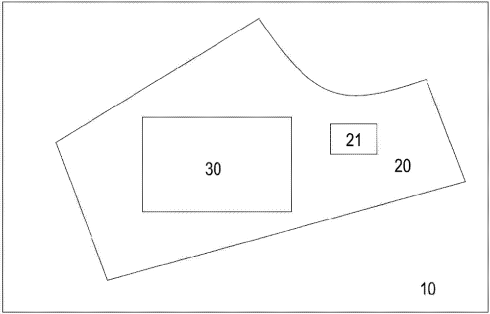
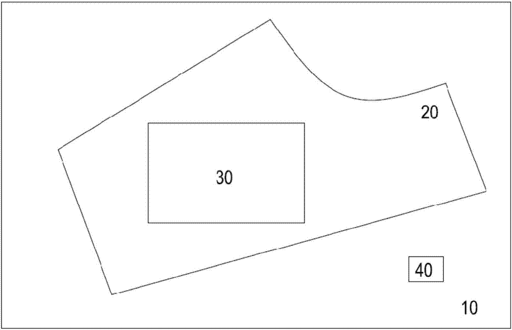
[0045] This embodiment is a method for realizing material positioning of a CNC cutting machine. Taking the processing and cutting of cloth by a CNC cutting machine as an example, the CNC cutting machine includes a workbench, an industrial camera and a numerical control system with a built-in computer control program. The method includes the following steps:

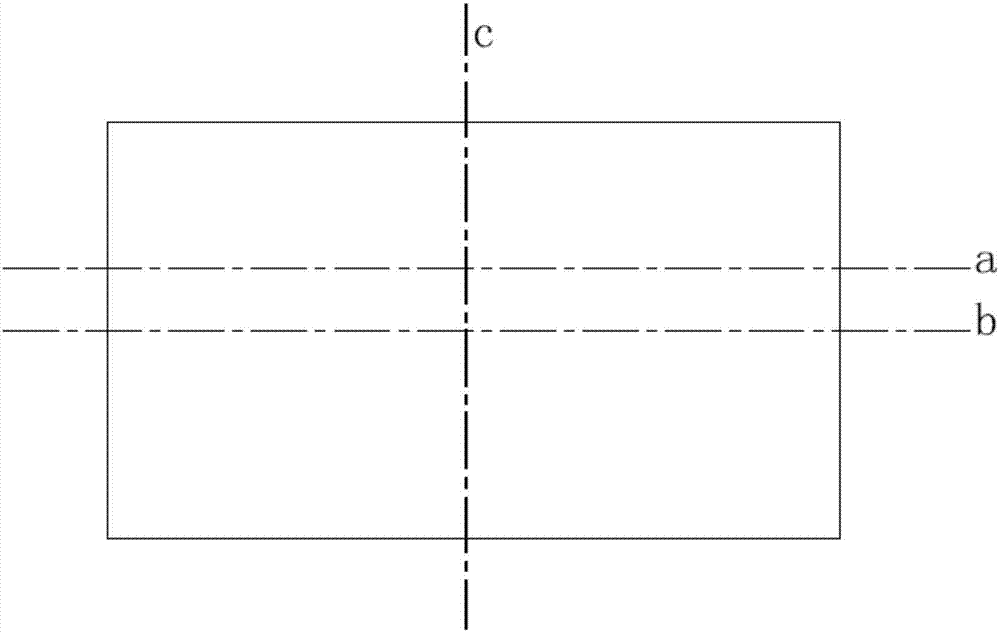
[0046] 1. Place the processed fabric on the workbench of the CNC cutting machine, and place a calibration ruler of an appropriate size on the fabric;

[0047] The workbench of CNC cutting machine equipment is dark in color. If the fabric to be processed is light in color, place it directly on the workbench; if the material to be processed is in da...


PUM


Abstract

The invention relates to the technical field of numerical-control cutting bed equipment, and particularly to a method of realizing material locating of numerical-control cutting bed equipment. The method is mainly applied to utilizing computer assistance for clothing machining and cutting, and includes the following steps: obtaining a bitmap image of machined material and a calibration scale; extracting a material contour and a calibration scale contour in the bitmap image, and respectively converting the same into vector data of the material contour and the calibration scale contour; using a size of the calibration scale in bitmap image and a pre-stored actual size of the calibration scale to carry out proportional transformation on the vector data of the material contour, and using a contour polygon, which is formed by vector data of a transformed material contour, to express an actual contour of the material; utilizing point data of the contour polygon and a trajectory polygon, which expresses a cutting trajectory, to calculate a transformation matrix; utilizing the transformation matrix to carry out geometric transformation on the trajectory polygon to obtain a transformed trajectory polygon; and judging whether the trajectory polygon completely falls inside the contour polygon, and if yes, finishing locating.

Description

technical field [0001] The invention relates to the technical field of numerical control cutting equipment, in particular to a method for realizing material positioning of the numerical control cutting equipment, which is mainly applied to garment processing and cutting with computer aids. Background technique [0002] Cutting is a major process in the manufacture of garments, which refers to the process of dividing the fabric into different geometric shapes required for sewing clothes, such as collars, sleeves... The clothing industry refers to these cut pieces of cloth as cut pieces. With the increase of labor costs, more and more enterprises use CNC cutting machines to replace people to complete the cutting work. The so-called CNC cutting machine is a CNC processing equipment with two-dimensional movable tools. It cuts the fabric according to the geometric shape of the piece expressed in coordinates stored in the computer. We call these geometric shape data the cutting ...

Claims


Application Information

Patent Timeline
Patent Type & Authority Applications(China)
IPC IPC(8): G06T7/00G06T7/73G06T7/66
CPCG06T7/0004G06T7/66G06T7/73G06T2207/10004G06T2207/30124
Inventor 李晗菲
Owner SHENZHEN BUYI TECH
Why Eureka
Try Eureka