
Method, device and system for vehicle fault monitoring, and vehicle

A vehicle failure and monitoring device technology, which is applied in the vehicle field, can solve problems such as transmission system failures that cannot be accurately identified, and achieve the effect of reducing potential safety hazards

Inactive Publication Date: 2017-12-22
BORGWARD AUTOMOTIVE CHINA CO LTD
View PDF0 Cites 8 Cited by
  • Summary
  • Abstract
  • Description
  • Claims
  • Application Information

AI Technical Summary

Problems solved by technology

[0003] The purpose of this disclosure is to provide a vehicle fault monitoring method, device, system and vehicle for the problem that the fault of the transmission system cannot be accurately identified in the prior art.

Method used


Image

  • Method, device and system for vehicle fault monitoring, and vehicle
  • Method, device and system for vehicle fault monitoring, and vehicle
  • Method, device and system for vehicle fault monitoring, and vehicle

Examples


Embodiment Construction

[0037] Specific embodiments of the present disclosure will be described in detail below in conjunction with the accompanying drawings. It should be understood that the specific embodiments described here are only used to illustrate and explain the present disclosure, and are not intended to limit the present disclosure.

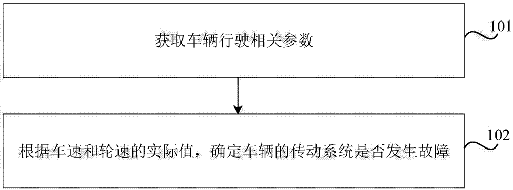
[0038] figure 1 is a flow chart of a vehicle fault monitoring method provided according to an embodiment of the present disclosure, such as figure 1 As shown, the method may include the following steps.

[0039] In step 101, vehicle running-related parameters are obtained, the vehicle running-related parameters at least including actual values ​​of vehicle speed and wheel speed.

[0040] Parameters related to vehicle driving can be obtained through corresponding sensors. For example, the actual value of the vehicle speed can be obtained by a vehicle speed sensor; the actual value of the wheel speed can be obtained by a wheel speed sensor.

[0041] In the ...


PUM


Abstract

The present disclosure relates to a vehicle failure monitoring method, device, system and vehicle. The method includes: acquiring vehicle running related parameters, the vehicle running related parameters at least including actual values ​​of vehicle speed and wheel speed; determining whether a transmission system of the vehicle fails according to the actual values ​​of vehicle speed and wheel speed. Thus, the transmission system failure can be judged and identified through the vehicle driving related parameters, and the failure monitoring of the vehicle transmission system can be realized. Moreover, it can provide support and basis for subsequent fault handling, which is beneficial to reduce potential safety hazards.

Description

technical field [0001] The present disclosure relates to the vehicle field, in particular, to a vehicle failure monitoring method, device, system and vehicle. Background technique [0002] The vehicle transmission system is generally composed of an electric motor, a transmission mechanism (including a gearbox and a differential), and a driving half shaft. The transmission system outputs the power from the electric motor to the wheels through the gearbox, differential, and drive shaft to generate driving force so that the vehicle can run at a certain speed. When there is a problem with the relative movement of the drive shaft and the differential gear of the transmission system (such as tooth slip between the input shaft and the bevel gear on the side of the differential, or abnormal wear of the connection between the output shaft and the sun gear, or other problems), The vehicle will experience drivetrain failure. When the transmission system breaks down, it can be identif...

Claims


Application Information

Patent Timeline
Patent Type & Authority Applications(China)
IPC IPC(8): B60R16/023
CPCB60R16/0234
Inventor 吕朝鹏
Owner BORGWARD AUTOMOTIVE CHINA CO LTD
Learn More