Roller washing machine

A technology of a drum washing machine and a clamping part, which is applied in the field of washing machines, can solve the problems of large moving displacement of the inner drum system, long time required for tightening bolts, difficulty in disassembly and maintenance, etc., so as to shorten the installation time, improve the installation efficiency, Easy to remove effect

Active Publication Date: 2017-12-22
WUXI LITTLE SWAN ELECTRIC CO LTD
View PDF3 Cites 4 Cited by
  • Summary
  • Abstract
  • Description
  • Claims
  • Application Information

AI Technical Summary

Problems solved by technology

[0002] At present, the motor of the drum washing machine is generally fixed on the outer tub of the washing machine by two bolts. The torque of each bolt is relatively large, and it takes a long time to tighten the bolts; Maintenance is more difficult. The sleeve cannot be inserted and disassembled in a natural state. It is necessary to move the entire inner cylinder system to the left to move the right bolt to the left. Generally, two people are required to complete this operation, and the displacement of the inner cylinder system is relatively large, which is easy Damage to the washing machine by pulling on internal wires and bumping internal parts

Method used


Image

  • Roller washing machine
  • Roller washing machine
  • Roller washing machine

Examples


Embodiment 1

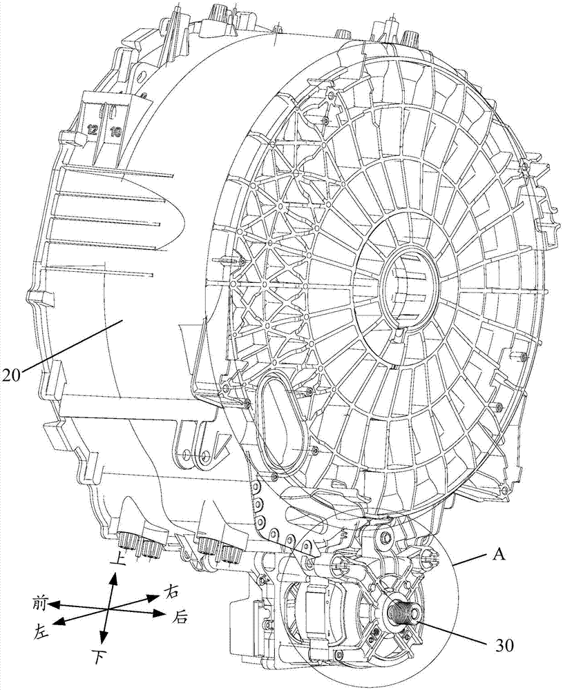
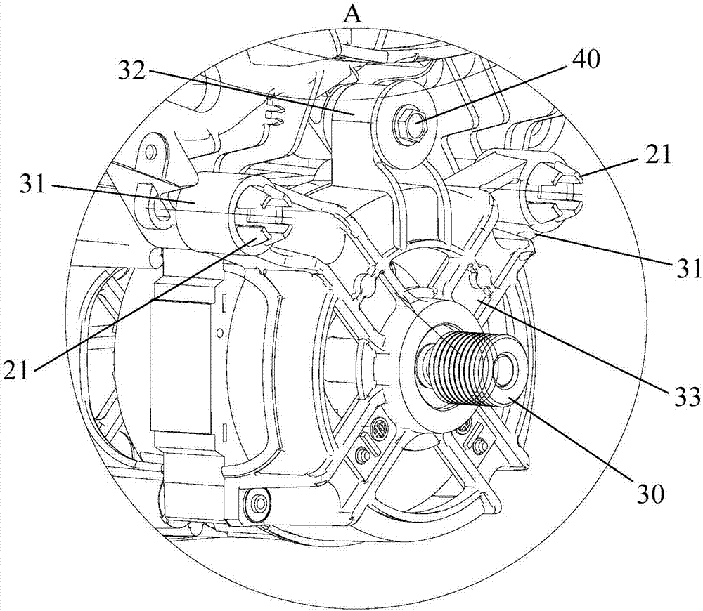
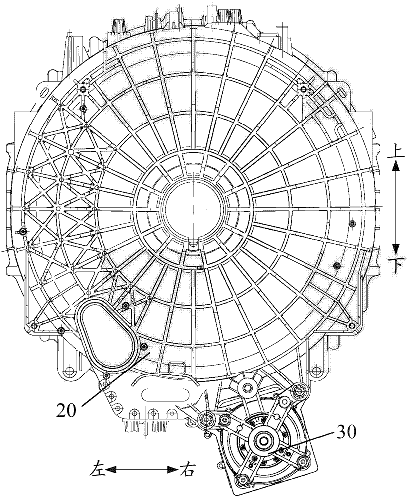
[0072] Embodiment one (as Figure 1 to Figure 12 shown)

[0073] The first engaging portion is the claw 21 , the second engaging portion is the insertion hole 311 , the claw 21 can pass through the insertion hole 311 and be hooked on the opening end of the insertion hole 311 , so that the motor 30 is engaged with the tub 20 .

[0074] The first clamping part is the claw 21, and the second clamping part is the socket 311. Then the claw 21 is inserted into the socket 311, and the top of the claw 21 can be automatically hooked on the opening end of the socket 311. Due to the structural limitation of the claw 21, the motor 30 cannot slide out no matter how it shakes under the action of an external force, and it has sufficient reliability, thereby realizing the clamping and fixing of the motor 30 and the outer barrel 20; and when assembling, only need to execute The insertion action is enough, and the claw 21 and the socket 311 will be automatically locked in place, which is very ...

Embodiment 2

[0116] Embodiment 2 (not shown in the figure)

[0117] The difference from the first embodiment is that the first engaging part is an insertion hole, and the second engaging part is a claw.

Embodiment 3

[0118] Embodiment three (not shown in the figure)

[0119] The difference from Embodiment 1 is that both the first clamping part and the second clamping part include claws and sockets, that is, claws and sockets are set on the outer barrel and the motor at the same time, and the claws on the outer barrel and the motor The jack on the outer barrel is compatible with the jack on the outer barrel and the claw on the motor.


PUM


Abstract

The invention provides a roller washing machine, which comprises a box body, an outer barrel and a motor; the outer barrel is installed in the box body, and a first buckling part is arranged on the outer barrel; a second buckling part matched with the first buckling part is arranged on the motor, and buckled with the first buckling part, thus the motor is buckled with the outer barrel. Theroller washing machine applies the buckling cooperation of the first buckling part and the second buckling part to realize the buckling and fixing of the motor and the outer barrel, and replace the method of fixing the motor by two bolts in the prior art, thus the installing difficulty of the motor is significantly reduced, the motor installing time is shortened, and the production efficiency of the roller washing machine is improved; meanwhile, the buckling method is convenient to dismount, and can be operated manually without tools; therefore, an inner cylinder system is not required to move, the labor force and materials are saved; moreover, damage of the washing machine cannot be caused by drawing internal leads and colliding to the spare parts at the inner part, the dismounting and repairing in the late period are facilitated.

Description

technical field [0001] The invention relates to the field of washing machines, in particular to a drum washing machine. Background technique [0002] At present, the motor of the drum washing machine is generally fixed on the outer tub of the washing machine by two bolts. The torque of each bolt is relatively large, and it takes a long time to tighten the bolts; Maintenance is more difficult. The sleeve cannot be inserted and disassembled in a natural state. It is necessary to move the entire inner cylinder system to the left to move the right bolt to the left. Generally, two people are required to complete this operation, and the displacement of the inner cylinder system is relatively large, which is easy Pulling on internal wires and bumping internal parts can cause damage to the washing machine. Contents of the invention [0003] In order to solve at least one of the above technical problems, the object of the present invention is to provide a drum washing machine. ...

Claims


Application Information

Patent Timeline
Patent Type & Authority Applications(China)
IPC IPC(8): D06F37/20D06F37/26
Inventor 郑汉卿张雷
Owner WUXI LITTLE SWAN ELECTRIC CO LTD
Why Eureka
Try Eureka