Arc suppression switch

A technology of electric gate and electric arc, applied in the direction of electrical components, etc., can solve problems such as danger and breakdown, and achieve the effect of ensuring normal power transmission and suppressing the generation of electric arc

Active Publication Date: 2017-12-22
厦门国电龙源电力发展有限公司
View PDF4 Cites 1 Cited by
  • Summary
  • Abstract
  • Description
  • Claims
  • Application Information

AI Technical Summary

Problems solved by technology

[0002] The switch is a commonly used power on-off device. Its main advantage is that the contacts are clearly visible and there is no internal indirect mechanism, which can completely ensure the on-off of the power line and has high safety. At the moment of contact or disengagement, the air gap between the tool rod and the static contact is easy to be broken down by the AC voltage, resulting in an obvious arc, which is dangerous

Method used


Image

  • Arc suppression switch
  • Arc suppression switch
  • Arc suppression switch

Examples


Embodiment 1

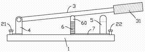
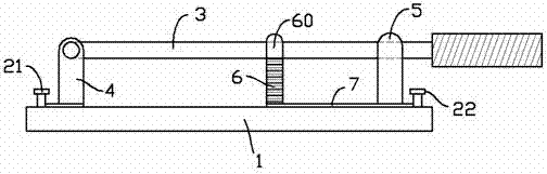
[0013] exist figure 1 , figure 2 In the first embodiment shown, the arc suppression switch includes a base 1, and a first terminal 21 and a second terminal 22 are arranged on both sides of the base 1; the first terminal 21 is electrically connected to the surrounding The hinge seat 4 for hinged knife bar 3, the second terminal 22 is electrically connected to the conductive bayonet seat 5 for clamping the knife bar 3 nearby; the rear end of the knife bar 3 is connected to an insulating knife handle31.

[0014] A buffer seat 6 is also provided between the conductive bayonet seat 5 and the hinge seat 4; the upper end of the buffer seat 6 is fixed with a metal bayonet 60 that can hold the knife rod 3; the metal bayonet 60 is connected in series with an inductor (set inside the buffer seat 6, not shown), and then electrically connected to the conductive bayonet seat 5 through the conductor 7; the height of the metal bayonet 60 on the buffer seat 6 satisfies the following conditi...

Embodiment 2

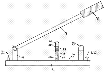
[0017] for image 3 The second embodiment shown is different from the first embodiment in that the buffer seat includes a fixed insulating tube 61 and a hollow sliding column 62 that can slide up and down inside the fixed insulating tube 61; the upper part of the hollow sliding column 62 The metal bayonet 60 is provided, and the lower part is provided with an induction coil 63 electrically connected to the metal bayonet 60; the bottom of the hollow sliding column 62 is connected to the bottom of the fixed insulating tube 61 through a compression spring 64; The fixed insulating tube 61 is also provided with a mixing column 65 coaxial with the fixed insulating tube 61. The upper part of the mixing column 65 is provided with a section of silicon steel column (unmarked), and the lower part is an insulating column; state, the hollow sliding column 62 is kept at the upper limit position under the elastic force of the compression spring 64, as image 3 As shown, the length of the si...


PUM


Abstract

The invention provides an arc suppression switch which includes a base. A first binding post and a second binding post are respectively arranged on the two sides of the base. The first binding post is electrically connected with a nearby hinge mount used for hinging a cutter bar. The second binding post is electrically connected with a nearby conductive bayonet mount used for clamping the cutter bar. A cushion mount is arranged between the conductive bayonet mount and the hinge mount. A metal bayonet for clamping the cutter bar is arranged at the upper end of the cushion mount. The metal bayonet is connected in series with an inductor, and then electrically connected with the conductive bayonet mount. The height of the metal bayonet on the cushion mount meets the following condition: when the cutter bar is closed, the cutter bar contacts the metal bayonet of the cushion mount first, and then contacts the conductive bayonet mount. The switch can suppress arcs in the opening/closing process, and is of high safety.

Description

technical field [0001] The invention relates to the field of electric equipment, in particular, to an electric switch blade. Background technique [0002] The switch is a commonly used power on-off device. Its main advantage is that the contacts are clearly visible and there is no internal indirect mechanism, which can completely ensure the on-off of the power line and has high safety. At the moment of contact or disengagement, the air gap between the tool holder and the static contact is easily broken down by the AC voltage, resulting in an obvious arc, which is dangerous to a certain extent. Contents of the invention [0003] In view of the above problems, the purpose of the present invention is to provide an arc suppression switch, which can suppress the generation of arc during the opening and closing process of the switch, and has good safety. [0004] The technical solution adopted by the present invention to solve the technical problem is: the arc suppression switc...

Claims


Application Information

Patent Timeline
Patent Type & Authority Applications(China)
IPC IPC(8): H01H21/56
CPCH01H21/56
Inventor 赵雅琴
Owner 厦门国电龙源电力发展有限公司
Why Eureka
Try Eureka