Perforating drill bit for orthopedic surgery

A technology of orthopedic surgery and drill bits, which is applied in the fields of surgery, medical science, etc., can solve the problem of damage to the surrounding tissues at the opening, and achieve the effects of improving the safety of use, facilitating disassembly and replacement, and avoiding injuries

Pending Publication Date: 2021-12-17
黎观保 +6
View PDF5 Cites 0 Cited by
  • Summary
  • Abstract
  • Description
  • Claims
  • Application Information

AI Technical Summary

Problems solved by technology

[0003] When the existing drilling drill is in use, the rotating mechanism drives the drill to rotate, so that the drill can open and ream the bone. When the existing drill is used in surgery, due to its integrated structure, when it is in the When the drill bit is too much hindered by the bone during rotation, if the rotation cannot be stopped in time, it is very easy to cause damage to the surrounding tissues at the opening. Therefore, we propose a perforating drill bit for orthopedic surgery

Method used


Image

  • Perforating drill bit for orthopedic surgery
  • Perforating drill bit for orthopedic surgery
  • Perforating drill bit for orthopedic surgery

Examples


Embodiment 1

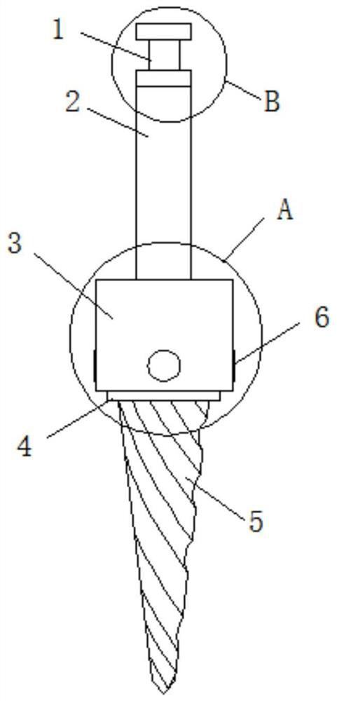
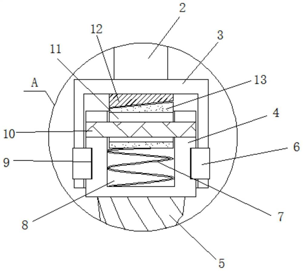
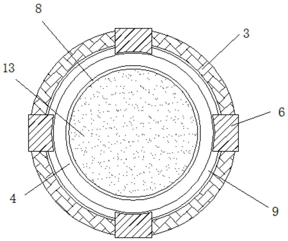
[0022] see Figure 1 to Figure 3 , the present invention provides a technical solution: a perforating drill for orthopedic surgery, comprising a drill body 5, the top of the drill body 5 is fixed with an end block 4, the top outer wall of the end block 4 is provided with a sleeve 3, and the end block 4 The outer wall of the sleeve is provided with a turning groove 9, and the side wall of the sleeve 3 is fixed with a side block 6. Through the designed sleeve 3, side block 6 and end block 4, the sleeve 3 is sleeved on the outer wall of the end block 4, both The mutual rotation connection is realized through the side block 6 to ensure that the drill shank 2 and the drill bit body 5 can rotate with each other without affecting each other. Groove 8, a top spring 7 is arranged inside the installation groove 8, through the designed top spring 7, an elastic force is applied to the sliding block 13 to ensure that its top end and the end surface of the transmission block 12 fit together...

Embodiment 2

[0024] see Figure 1 to Figure 4 , the present invention provides a technical solution: a perforating drill for orthopedic surgery, comprising a drill body 5, the top of the drill body 5 is fixed with an end block 4, the top outer wall of the end block 4 is provided with a sleeve 3, and the end block 4 The outer wall of the sleeve is provided with a turning groove 9, and the side wall of the sleeve 3 is fixed with a side block 6. Through the designed sleeve 3, side block 6 and end block 4, the sleeve 3 is sleeved on the outer wall of the end block 4, both The mutual rotation connection is realized through the side block 6 to ensure that the drill shank 2 and the drill bit body 5 can rotate with each other without affecting each other. Groove 8, a top spring 7 is arranged inside the installation groove 8, through the designed top spring 7, an elastic force is applied to the sliding block 13 to ensure that its top end and the end surface of the transmission block 12 fit together...


PUM


Abstract

The invention discloses a perforating drill bit for orthopedic surgery. The perforating drill bit comprises a drill bit body, wherein an end block is fixed to the top end of the drill bit body, a sleeve sleeves the outer wall of the top end of the end block, a rotating groove is formed in the outer wall of the end block, a side block is fixed to the side wall of the sleeve in a penetrating mode, one end of the side block extends into the rotating groove, a mounting groove is formed in the top end of the end block, and a top spring is arranged in the mounting groove. According to the perforating drill bit, the sleeve, the side block and the end block are designed, the sleeve sleeves the outer wall of the end block, the sleeve and the end block are rotationally connected through the side block, a drill handle and the drill bit body can rotate relative to each other and do not affect each other, the top spring is designed to apply elastic extrusion to a sliding block, the top end of the sliding block is attached to the end face of a transmission block, and power transmission is achieved.

Description

technical field [0001] The invention belongs to the technical field of orthopedic surgery, in particular to a drilling drill for orthopedic surgery. Background technique [0002] Drill bits for orthopedic surgery are fired from nickel-based powder, and undergo plasma sulfurizing and nitriding processes. After sintering, segmental annealing makes the microstructure of the material uniform, and the nitriding process and plasma sulfurizing improve the surface hardness and hardness of the workpiece. Strength and oxidation resistance, a drill bit used in orthopedics to open and ream bones, which is installed on a rotating mechanism for rotation. [0003] When the existing drilling drill is in use, the rotating mechanism drives the drill to rotate, so that the drill can open and ream the bone. When the existing drill is used in surgery, due to its integrated structure, when it is in the When the drill bit is too much hindered by the bone during rotation, if the rotation cannot be...

Claims


Application Information

Patent Timeline
Patent Type & Authority Applications(China)
IPC IPC(8): A61B17/16
CPCA61B17/16A61B17/1615A61B17/1617
Inventor 黎观保黎品泉唐海陈秋安周伟马鹏刘桐源
Owner 黎观保
Why Eureka
Try Eureka