Relay improvement structure

A technology of improving structure and relay, applied in relays, electromagnetic relays, detailed information of electromagnetic relays, etc., can solve the problems of springs that cannot be reset, misunderstanding of fault judgment, reliability affecting the reliability of power systems, etc., to increase the safety distance, Guaranteed the effect of absolute contact

Active Publication Date: 2017-12-22
ZHEJIANG IND & TRADE VACATIONAL COLLEGE
View PDF6 Cites 4 Cited by
  • Summary
  • Abstract
  • Description
  • Claims
  • Application Information

AI Technical Summary

Problems solved by technology

[0004] The reliability of the relay directly affects the reliability of the entire power system. The electrical contact is one of the key components of the relay, and its performance is directly related to the electrical performance of the relay. The common relay is an electromagnetic current relay, which conducts through the coil to make The iron core is magnetic, thereby attracting the armature, driving the mechanical device to close the normally open contact and disconnect the normally closed contact. If the relay is powered off, the moving contact will return to its original position under the action of the recovery spring. The normally open contact of the ordinary relay Both the head and the normally closed contact are static contacts. The spring will cause elastic fatigue due to long-term use, which will cause the spring to fail to return to its original position, resulting in the moving contact not being able to effectively touch the normally closed contact. Or, because the distance between the normally open contact and the moving contact is small, the moving contact touches the normally open contact when the iron core is not in action, causing certain misunderstandings to the fault judgment, and in severe cases, causing the entire power system to be paralyzed , resulting in unpredictable losses

Method used


Image

  • Relay improvement structure
  • Relay improvement structure
  • Relay improvement structure

Examples


Embodiment Construction

[0031] The following will clearly and completely describe the technical solutions in the embodiments of the present invention with reference to the accompanying drawings in the embodiments of the present invention. Obviously, the described embodiments are only some, not all, embodiments of the present invention. Based on the embodiments of the present invention, all other embodiments obtained by persons of ordinary skill in the art without making creative efforts belong to the protection scope of the present invention.

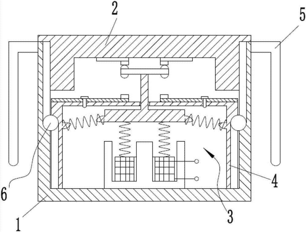
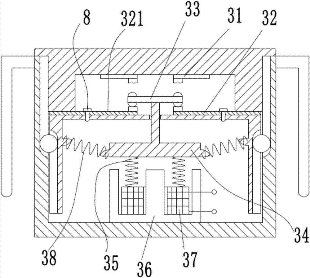
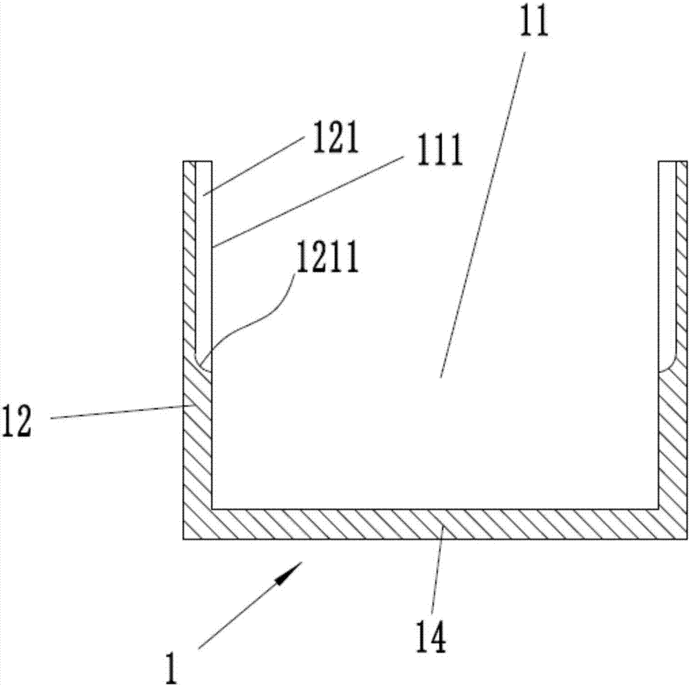
[0032] refer to Figure 1 to Figure 10 ,Such as figure 1 and figure 2 The improved relay structure shown includes a housing 1, an upper cover 2, a control system 3, a slider 4, terminals 5, steel balls 6, gaps 7 and screws 8, and the control system 3 is located in the inner cavity 11 of the housing 1 , the upper cover 2 is fastened on the top of the housing 1, the terminal 5 extends from the terminal extension hole 122 of the housing 1, and is placed outsid...


PUM


Abstract

The present invention discloses a relay improvement structure. The structure comprises a housing, an upper cover, a control system, a sliding block, terminals, steel balls, a gap and screws. The control system is located in the inner cavity of the housing, the upper cover is buckled on the housing, the terminals are extended out of the terminal extension holes of the housing and are arranged at the external portion of the housing after bending once, the control system comprises normally closed contacts, normally open contacts, a moving contact, an armature, a reset spring, an iron core, coils and springs, and the normally open contacts can be move up and down. The normally closed contacts and the normally open contacts are mutually moved to generate touch to indirectly increase the safety distance between the normally closed contacts and the normally open contacts and ensure the absolute contact of the moving contact and the normally closed contacts in a reset state so as to ensure the safe and reliable operation of the relay improvement structure.

Description

technical field [0001] The invention relates to the field of relay structures, in particular to an optimized structure of relays with a safer and more reliable control system. Background technique [0002] Electromagnetic relay is an electronic control device, which has a control system (also known as input circuit) and a controlled system (also known as output circuit), usually used in automatic control circuits, it actually uses a smaller current to control a larger An "automatic switch" for high currents. [0003] Chinese patent CN102446659B discloses an optimized structure of a relay, including: a body with at least a pair of positioning blocks arranged on opposite sides of the body, for locking the base plate when the body is placed in the mounting hole, so that the A part of the body is located on one side of the substrate, and a part is located on the other side of the substrate; and a plurality of terminals are separately arranged on the opposite side of the body, w...

Claims


Application Information

Patent Timeline
Patent Type & Authority Applications(China)
IPC IPC(8): H01H50/56H01H50/18
CPCH01H50/18H01H50/56
Inventor 姚锡钦林烨
Owner ZHEJIANG IND & TRADE VACATIONAL COLLEGE
Why Eureka
Try Eureka