Constant conduction time type boosting voltage stabilizer

A voltage regulator and conduction technology, which is applied in the field of constant on-time boost regulators, can solve the problems of large parasitic resistance load capacitance and large frequency variation range, and achieve the effect of optimizing the load regulation rate

Active Publication Date: 2017-12-22
WUXI ETEK MICROELECTRONICS
View PDF2 Cites 13 Cited by
  • Summary
  • Abstract
  • Description
  • Claims
  • Application Information

AI Technical Summary

Problems solved by technology

[0005] The present invention proposes a novel COT type BOOST voltage regulator, which can solve the

Method used


Image

  • Constant conduction time type boosting voltage stabilizer
  • Constant conduction time type boosting voltage stabilizer
  • Constant conduction time type boosting voltage stabilizer

Examples


Embodiment Construction

[0019] In order to make the above objects, features and advantages of the present invention more comprehensible, the present invention will be further described in detail below in conjunction with the accompanying drawings and specific embodiments.

[0020] Reference herein to "one embodiment" or "an embodiment" refers to a particular feature, structure or characteristic that can be included in at least one implementation of the present invention. "In one embodiment" appearing in different places in this specification does not all refer to the same embodiment, nor is it a separate or selective embodiment that is mutually exclusive with other embodiments. Unless otherwise specified, the words connected, connected, and joined in this document mean that they are electrically connected directly or indirectly.

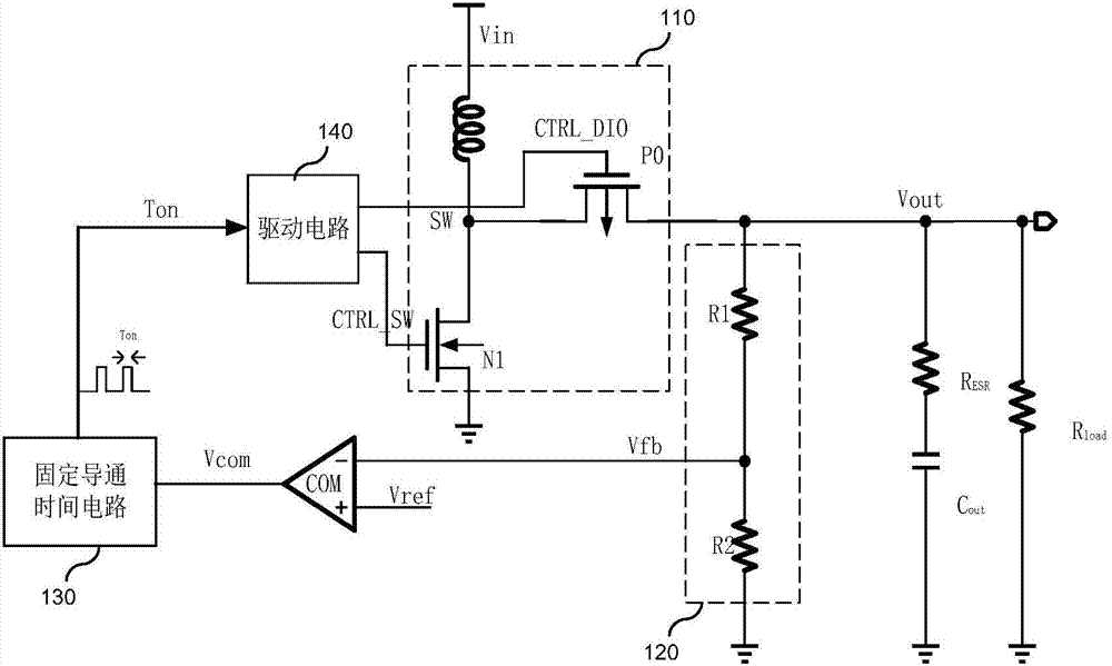
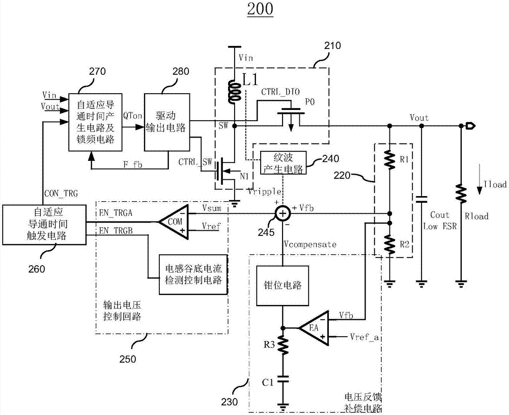
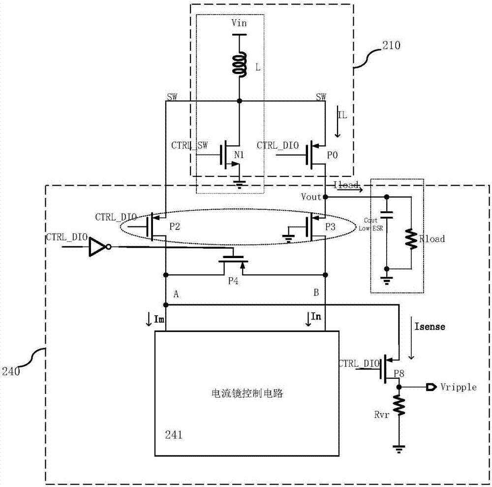
[0021] figure 2 It is a structural block diagram of the COT type BOOST regulator 200 in an embodiment of the present invention. The BOOST regulator 200 includes an outpu...


PUM


Abstract

The invention provides a constant conduction time type boosting voltage stabilizer. The constant conduction time type boosting voltage stabilizer comprises an output circuit, a voltage feedback circuit, a voltage feedback compensation circuit, a ripple generation circuit, a signal addition and subtraction circuit, an output voltage control circuit, a self-adaptive conduction time trigger circuit, a self-adaptive conduction time production circuit, a frequency locking circuit and a driving output circuit. The voltage feedback circuit is used for sampling output voltage to obtain feedback voltage. The voltage feedback compensation circuit is used for sampling output voltage to obtain feedback compensation voltage; a ripple production circuit is used for sampling inductive current in the output circuit to generate ripple voltage; the signal addition and subtraction circuit is used for using the feedback voltage to add the ripple voltage and to subtract the feedback compensation voltage to obtain a feedback resultant signal; the output voltage control circuit obtains a trigger enabled signal on the basis of the feedback resultant signal; the self-adaptive conduction time trigger circuit obtains the conductive trigger signal on the basis of the trigger enabled signal; the self-adaptive conduction time generation circuit and the frequency locking circuit are used for obtaining a quasi-fixed conduction time on the basis of the conduction trigger signal; and the driving output circuit generates a driving signal according to the quasi-fixed conduction time in order to drive the output circuit. The constant conduction time type boosting voltage stabilizer solves problem that a load end needs to use a electrolytic capacitor of a large parasitic resistor.

Description

【Technical field】 [0001] The invention relates to the field of voltage regulation, in particular to a constant conduction time boost voltage regulator. 【Background technique】 [0002] Boost (Boost) regulators are widely used in various consumer handheld devices and portable electronic products, which can convert the voltage of a single ordinary battery (NiCd, NiMH or dry battery, etc.) to a higher voltage required by the system . At present, most of these Boost regulators use current mode control. Although the current mode technology is relatively mature, it requires slope compensation, and the poor design of the compensation circuit will not only affect the stability of the system but also affect the working efficiency of the system. In recent years, Boost regulators with a constant on-time COT architecture have been widely adopted. [0003] figure 1 It is a structural block diagram of a traditional COT type BOOST regulator. Such as figure 1 As shown, the BOOST regula...

Claims


Application Information

Patent Timeline
IPC IPC(8): H02M3/158H02M1/088
CPCH02M1/088H02M3/158
Inventor 黄星星王国鹏夏勇杰陈照
Owner WUXI ETEK MICROELECTRONICS
Why Eureka
Try Eureka