Method for detecting local interlayer peeling position of composite material board

A composite material board and detection method technology, applied in the direction of analyzing materials, using sound waves/ultrasonic waves/infrasonic waves for material analysis, measuring devices, etc., can solve problems that are difficult to meet and affect detection results, and achieve the elimination of environmental noise. Meaning, effect that reinforces the effect

Active Publication Date: 2017-12-26
HOHAI UNIV
View PDF4 Cites 1 Cited by
  • Summary
  • Abstract
  • Description
  • Claims
  • Application Information

AI Technical Summary

Problems solved by technology

However, these methods generally need to predict the approximate location of the damage, and the location of the delamination must be easily accessible, which is difficult to meet in practical applications.
However, based on the vibration deformation of composite material plates, the formation of multi-precision second-order mixed partial derivatives of shear strain with clear physical meaning, and the research on detecting local delamination of composite material plates has not been reported yet.
[0003] Local delamination detection methods based on ultrasonic waves, electromagnetic fields, eddy currents, etc. are very sensitive to noise in the test environment. In the field test environment, the noise components are likely to cover up the real local delamination information and affect the detection effect.

Method used


Image

  • Method for detecting local interlayer peeling position of composite material board
  • Method for detecting local interlayer peeling position of composite material board
  • Method for detecting local interlayer peeling position of composite material board

Examples


Embodiment Construction

[0034] Below in conjunction with accompanying drawing, technical scheme of the present invention is described in further detail:

[0035] Those skilled in the art can understand that, unless otherwise defined, all terms (including technical terms and scientific terms) used herein have the same meaning as commonly understood by one of ordinary skill in the art to which this invention belongs.

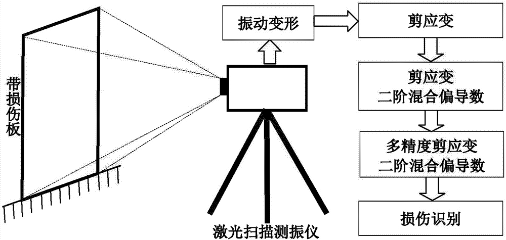
[0036] Such as figure 1 As shown, the method for detecting the local interlaminar peeling position of the composite material plate proposed by the present invention comprises the following steps:

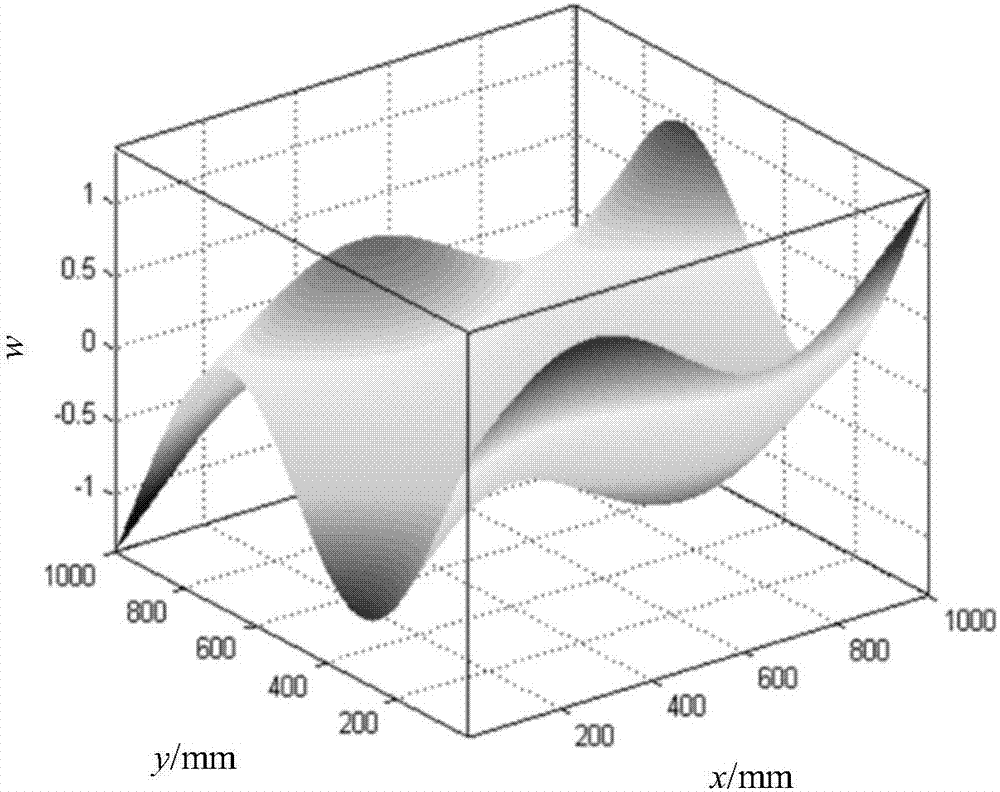
[0037] 1. Obtain the vibration deformation w(x,y) of the composite material plate;

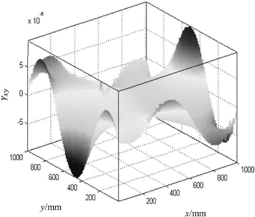
[0038] 2. Substitute w(x,y) into the shear strain formula of the plate to obtain the shear strain γ xy (x,y):

[0039]

[0040] Among them, x, y, and z are the coordinates of the length, width, and thickness directions of the plate, respectively.

[0041] 3. Apply the second-order mixed partial derivati...


PUM


Abstract

The invention discloses a method of detecting a local interlayer peeling position of a composite material board. The method comprises the following steps: measuring the vibration deformation of a composite material board; substituting the vibration deformation into a shearing strain formula of the board to obtain shearing strain; applying a second order mixed partial derivative operator to the shearing strain to obtain a shearing strain second order mixed partial derivative; folding the shearing strain second order mixed partial derivative and a multi-precision Spline function to obtain a multi-precision shearing strain second order mixed partial derivative; judging whether local interlayer peeling happens or not according to the result whether an abnormal peak value appears in the multi-precision shearing strain second order mixed partial derivative; and determining the local interlayer peeling position according to the peak value. The provided method can be used to analyze the vibration deformation of a composite material board, can judge whether local interlayer peeling happens or not, and positions the interlayer peeling. The multi-precision shearing strain second order mixed partial derivative with definite physical meaning is adopted as the damage index, the influence of environmental noise can be eliminated, and the damage characteristics are obviously enhanced.

Description

technical field [0001] The invention discloses a damage position detection method of a composite material plate, and specifically relates to the technical field of plate structure damage detection. Background technique [0002] Composite panels are prone to micro-local delamination under impact, and these micro-local delaminations will continue to expand, resulting in delamination buckling and even overall instability and failure of the structure. Therefore, it is of great significance to timely and effectively diagnose the local delamination of the micro-shock of the composite material plate. At present, local non-destructive testing methods based on ultrasonic, electromagnetic field, eddy current, etc. have been widely used in the detection of local delamination of composite material plates. However, these methods generally need to predict the approximate location of the damage, and the delamination location must be easily accessible, which is difficult to meet in practic...

Claims


Application Information

Patent Timeline
IPC IPC(8): G01N29/04
CPCG01N29/045G01N2291/0231G01N2291/0289G01N2291/2632
Inventor 沙刚刚曹茂森彭家意
Owner HOHAI UNIV
Why Eureka
Try Eureka