
Electric heating water cup

An electric hot water cup and hot water cup technology, which is applied to water boiling appliances, kitchen utensils, household appliances, etc., can solve the problems of affecting the heating efficiency and heating time of water in the cup, and the large amount of steam discharged.

Active Publication Date: 2017-12-29
ZHEJIANG SHAOXING SUPOR DOMESTIC ELECTRICAL APPLIANCE CO LTD
View PDF12 Cites 3 Cited by
  • Summary
  • Abstract
  • Description
  • Claims
  • Application Information

AI Technical Summary

Problems solved by technology

[0004] However, since the water outlet hole also acts as a steam hole, and considering that the water flows out smoothly when drinking water, the water outlet hole is generally made larger, but when the water outlet hole is made larger, it will cause excessive steam discharge, which will affect the cup. Water heating efficiency and heating time

Method used


Image

  • Electric heating water cup
  • Electric heating water cup
  • Electric heating water cup

Examples


Embodiment 1

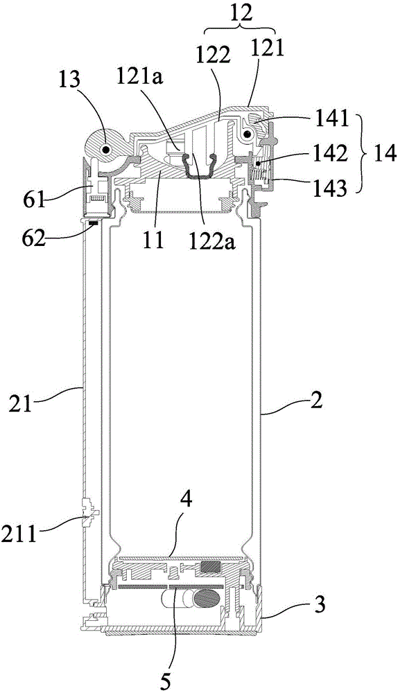
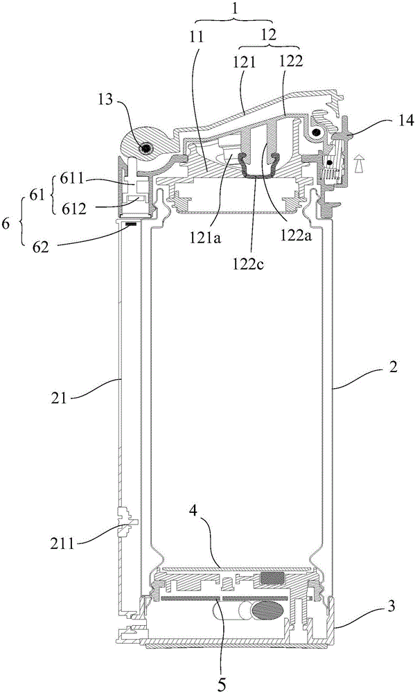
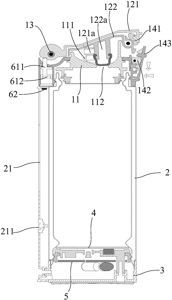
[0034] figure 1 A cross-sectional view of the structure of the electric hot water cup in a closed state provided by Embodiment 1 of the present invention. figure 2 A cross-sectional view of the structure of the electric water cup when the first upper cover is opened is provided for Embodiment 1 of the present invention. image 3 A cross-sectional view of the structure of the electric water cup when the first upper cover and the second upper cover are opened according to Embodiment 1 of the present invention. Figure 4 A cross-sectional view of the structure of the electric water cup when both the first hole and the second hole are opened according to Embodiment 1 of the present invention. Figure 5 The three-dimensional structure diagram of the electric water cup provided by Embodiment 1 of the present invention when the first upper cover is opened. Figure 6 The three-dimensional structure diagram of the electric water cup provided by Embodiment 1 of the present invention ...

Embodiment 2

[0053] Figure 8 The three-dimensional structure diagram of the electric water cup provided by Embodiment 2 of the present invention when both the first upper cover and the second upper cover are opened. On the basis of the above-mentioned embodiments, this embodiment provides an electric water cup with another structure, refer to the attached Figure 8 As shown, the difference between the electric water cup of the present embodiment and the first embodiment is that: the second upper cover 122 is provided with an accommodating groove 1221 matching the shape of the first upper cover 121, and the through hole 122b is opened in the groove of the accommodating groove 1221 At the bottom, the first upper cover 121 is set in the accommodating groove 1221 .

[0054] That is to say, in this embodiment, the size of the second upper cover 122 is larger than the size of the first upper cover 121, by setting up a receiving groove 1221 in the area corresponding to the first hole 111 on the...


PUM


Abstract

The invention provides an electric heating water cup which comprises a cup cover (1) and a cup body (2). The cup cover (1) comprises a lower cover assembly (11) and an upper cover assembly (12). A first hole (111) and a second hole (112) are formed in the lower cover assembly (11). The upper cover assembly (12) comprises a first upper cover (121) for opening or closing the first hole (111) and a second upper cover (121) for opening or closing the second hole (111). The first upper cover (121) and the second upper cover (122) are rotatably connected with the lower cover assembly (11) through the same rotating shaft (13). The rotation range of the second upper cover (122) is between the first upper cover (121) and the lower cover assembly (11). When heating water, the first cover is opened to expose the first hole so that steam is discharged from the first hole to ensure the heating safety and heating efficiency; when drinking water, the second cover is opened to expose the second hole so that the water flows out of the second hole. The electric heating water cup is easy to use.

Description

technical field [0001] The invention relates to the technical field of household appliances, in particular to an electric water cup. Background technique [0002] The electric hot water cup has the advantages of fast heating speed, simple use, and portability, and has become a common electrical appliance in people's daily life. [0003] The electric hot water cup in the prior art includes a cup cover and a cup body. The top of the cup body has an opening. The cup cover is provided with a water outlet hole. When the electric hot water cup is heated, the water vapor in the cup body gradually increases with the increase of the water temperature, and the generated water vapor gathers inside the cup body, causing the air pressure inside the electric hot water cup to be too high and dangerous. Therefore, when heating, the cup cover is unscrewed from the cup body to open the water outlet hole, so that the steam generated during heating is discharged from the water outlet hole, pr...

Claims


Application Information

Patent Timeline
IPC IPC(8): A47J27/21
CPCA47J27/21008A47J27/21158A47J27/21166
Inventor 史庭飞黄理水王国栋
Owner ZHEJIANG SHAOXING SUPOR DOMESTIC ELECTRICAL APPLIANCE CO LTD
Learn More