Filter and filtering and cleaning method thereof

A filter and filter screen technology, applied in chemical instruments and methods, fixed filter element filters, filtration and separation, etc., can solve problems such as affecting the normal flow of the main pipeline, and achieve the effect of convenient and fast operation.

Pending Publication Date: 2017-12-29
MAANSHAN NBWAVE HEAT ENERGY SCI
View PDF3 Cites 0 Cited by
  • Summary
  • Abstract
  • Description
  • Claims
  • Application Information

AI Technical Summary

Problems solved by technology

[0007] Aiming at the problem that the normal circulation of the main pipeline is affected when the filter

Method used


Image

  • Filter and filtering and cleaning method thereof
  • Filter and filtering and cleaning method thereof
  • Filter and filtering and cleaning method thereof

Examples


Example Embodiment

[0048] Example 1

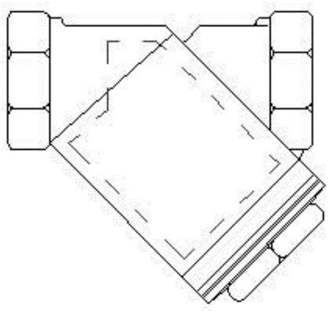
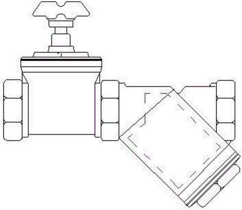
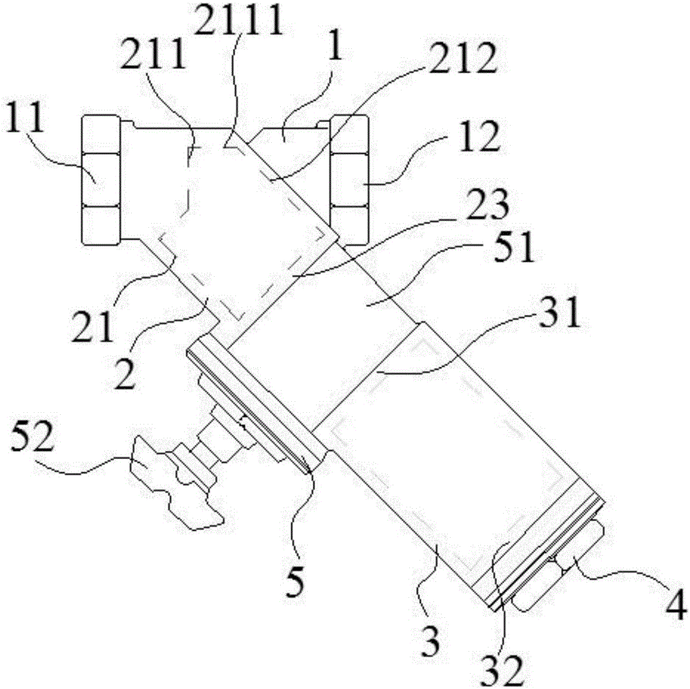
[0049] Such as image 3 As shown, a filter includes an interception lumen 1, a filter mesh 21 and a filter lumen 2. The interception lumen 1 is located on the axis of the main pipeline, and the filter lumen 2 and the interception lumen 1 is connected, the filter mesh 21 is located in the filter tube cavity 2, the filter mesh water intake port 211 of the filter mesh 21 is located in the interception tube cavity 1, and the filter mesh water intake port 211 is directly facing the liquid flow direction. It includes a valve 5 and a sedimentation chamber 3. One end of the valve 5 communicates with the end of the filter tube cavity 2 away from the interception tube 1, and the other end of the valve 5 communicates with the sedimentation chamber 3.

[0050] The filter mesh water inlet 211 of the filter mesh 21 of the filter is directly facing the liquid flow direction on the main pipe, so that the filter mesh water intake port 211 of the filter mesh 21 intercepts impurit...

Example Embodiment

[0056] Example 2

[0057] Such as image 3 As shown, a filter of this embodiment is different from Embodiment 1 in that the water inlet 211 of the filter 21 includes a top surface 2111 of the filter and a side surface 212 of the filter, and the water inlet 211 of the filter The edge of the filter mesh and the top surface 2111 of the filter are in contact with the inner wall of the interception lumen 1, the top surface 2111 of the filter is in contact with the highest point of the inner wall of the interception lumen 1, and the lowest point of the water inlet 211 of the filter is in contact with the interception lumen 1.

[0058] In order to prevent the liquid from not passing through the interception effect of the filter screen 21, from the interception lumen 1 directly into the main pipeline behind the interception lumen 1, affecting the water quality index content in the main pipeline, the filter 21 and the interception lumen 1 and the filter lumen The fit design of 2 is zero fi...

Example Embodiment

[0059] Example 3

[0060] Such as image 3 As shown, a filter of this embodiment is different from Embodiment 1 or 2 in that the angle between the axis of the filter lumen 2 and the axis of the interception lumen 1 is 30°-45°. In specific applications, you can choose to set angle values ​​such as 30°, 45°, 35°, 40°, 38°, and 43°.

[0061] The filter screen 21 is located in the filter tube cavity 2, and the angle between the axis of the filter screen 21 and the axis of the interception tube cavity 1 is 30°-45°. The impurities pass through the water inlet 211 of the filter screen and are intercepted by the filter screen side 212 of the filter screen 21 When it comes down, the intercepted impurities will fall into the filter mesh 21 under the action of gravity and the scouring effect of the liquid, and enter the sedimentation chamber 3 along the direction of the filter lumen 2. When the angle is in the range of 30°-45° , The impurities will not be blocked on the side 212 of the filt...


PUM

PropertyMeasurementUnit
Axis angleaaaaaaaaaa

Abstract

The invention discloses a filter and a filtering and cleaning method thereof, belonging to the technical field of filters. It includes an interception lumen, a filter screen and a filter lumen, the interception lumen is located on the axis of the main pipeline, the filter lumen communicates with the interception lumen, and the filter net is located in the filter In the lumen, the water intake port of the filter screen is located in the interception lumen, and the water intake port of the filter screen is facing the direction of liquid flow, and also includes a valve and a sedimentation chamber, one end of the valve and the end of the filter lumen away from the interception lumen The other end of the valve communicates with the sedimentation chamber. Aiming at the problem of affecting the normal circulation of the main pipeline when the filter is cleaned in the prior art, the filter can be cleaned without affecting the normal circulation of the main pipeline.

Description

technical field [0001] The invention relates to the technical field of filters, in particular to a filter and a filtering and cleaning method thereof. Background technique [0002] The filter plays the role of filtering. When the fluid medium passes through the filter, the impurities are filtered and collected by the filter element. When cleaning is required, the filter element can be taken out, the impurities on the filter element are removed, and then the filter element is put into the filter. In the Y-shaped filter of the prior art, when the diameter of the filter inlet and outlet is small, the diameter of the filter element is correspondingly small, resulting in a small filter area, poor filtering capacity, high frequency of cleaning or replacing the filter element, and In the process of cleaning or replacing the filter element, it is necessary to cut off the pipeline front and back, which will delay the normal production operation, affect the production efficiency and b...

Claims


Application Information

Patent Timeline
IPC IPC(8): B01D29/11B01D29/94B01D35/02
CPCB01D29/11B01D29/94B01D35/02
Inventor 吴剑峰
Owner MAANSHAN NBWAVE HEAT ENERGY SCI
Why Eureka
Try Eureka