
Linear fire work separation device

A pyrotechnic separation device and linear technology, applied in the field of separation systems, can solve the problems of affecting equipment, residual pollution and large impact force, etc., and achieve the effect of rapid separation

Inactive Publication Date: 2017-12-29
BEIJING INST OF ELECTRONICS SYST ENG
View PDF5 Cites 7 Cited by
  • Summary
  • Abstract
  • Description
  • Claims
  • Application Information

AI Technical Summary

Problems solved by technology

[0005] Another object of the present invention is to provide a pyrotechnic separation device to solve the problem of residual pollution and large impact force affecting equipment in the prior art separation

Method used

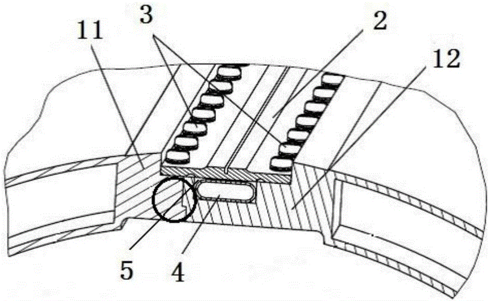

Image

  • Linear fire work separation device
  • Linear fire work separation device
  • Linear fire work separation device

Examples


Embodiment Construction

[0022] In order to illustrate the present invention more clearly, the present invention will be further described below in conjunction with preferred embodiments and accompanying drawings. Similar parts in the figures are denoted by the same reference numerals. Those skilled in the art should understand that the content specifically described below is illustrative rather than restrictive, and should not limit the protection scope of the present invention. It should be noted that the "upper" and "lower" in the present invention refer to the up-down direction shown in the drawings. For example, the "upper surface" mentioned in the present invention refers to the upper direction shown in the drawings.

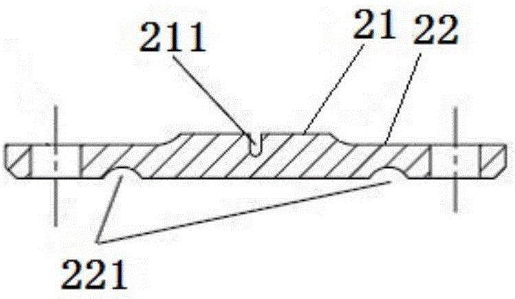
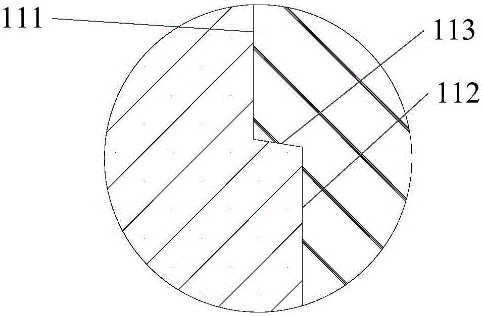
[0023] The invention provides a linear pyrotechnic separation device, such as figure 1 As shown, the pyrotechnic separation device includes a separation plate 2 and a separation component, and the separation component includes a first separation part 11 and a second separation pa...


PUM


Abstract

The invention provides a linear fire work separation device. The linear fire work separation device comprises a separation plate and a separation component. The separation component comprises a first separation part and a second separation part combined with the first separation part. The separation plate is fixedly connected with the first separation part and the second separation part. The upper surface of the first separation part or the second separation part is sunken inwards, and thus a containing groove is formed. The separation plate covers an opening of the containing groove. A load expansion pipe is mounted in the containing groove. An inward-sunken separation groove is formed in the upper surface of the separation plate in the axial direction and located above the containing groove. According to the linear fire work separation device, rapid separation can be achieved in a compact small-sized space, and the situation that residual pollution generated by the explosive load is dispersed into a space storing the separation device and consequently equipment in the space is damaged is avoided.

Description

technical field [0001] The present invention relates to the field of separation systems. More specifically, it relates to a linear pyrotechnic separation device. Background technique [0002] The pyrotechnic separation device is used to generate explosive force such as gunpowder and other explosive loads to cut off the connecting parts to achieve the purpose of separation. It is widely used in the separation of stages in spacecraft, the separation of satellites and rockets, and the separation of fairings. However, the stable connection of the parts before the separation in the prior art brings certain difficulties to the explosive separation. Therefore, the traditional explosive load is generally high, and the impact load of the pyrotechnic separation device is relatively large, and the impact force is strong. In a compact size space The impact force of the explosion in the medium cannot be resolved and affect other devices, and there are various equipment in the separation...

Claims


Application Information

Patent Timeline
IPC IPC(8): B64G1/64
Inventor 张永超
Owner BEIJING INST OF ELECTRONICS SYST ENG
Learn More