
Gas insulated switchgear

Active Publication Date: 2014-07-10
LSIS CO LTD
View PDF9 Cites 1 Cited by
  • Summary
  • Abstract
  • Description
  • Claims
  • Application Information

AI Technical Summary

Benefits of technology

This patent describes a gas insulated switchgear that has two cam surfaces that control the movement of a movable contact arm. The first cam surface determines the initial movement of the arm during a breaking operation, while the second cam surface controls the movement at a later stage. The first cam surface is faster and shorter than the second surface, allowing for quick separation of the contact arms at the initial stage and positioning them at a longer distance during the late stage. Additionally, a third cam surface can be included to have a different average slope and a recess can be added to prevent excessive movement of the contact arms. Overall, the switchgear has improved breaking performance and can easily adjust the movement characteristics of the movable contact arm.

Problems solved by technology

To this end, however, a large capacity actuator is required.
In detail, in order to increase actuating power, a large capacity spring needs to be used, which, however, results in an increase in a volume of the actuator.
However, even with the related art, a time during which maximum torque is transmitted is too short and the decrement of torque based on a movement of a movable contact arm is too large, so it is difficult to obtain a sufficient breaking speed.
Namely, in order to perform a breaking operation with maximum acceleration force at the initiation of the breaking operation, maximum torque needs to last as long as possible or the decrement of torque needs to be small, but in the related art, it is impossible to adjust the duration or the decrement.
In addition, in order to maximize acceleration with which the movable contact arm is moved in a state in which the breaking operation is performed to a degree, the better a time interval during which maximum torque and minimum torque is applied is shorter, but with the related art, it is impossible to adjust the time interval.

Method used


Image

  • Gas insulated switchgear
  • Gas insulated switchgear
  • Gas insulated switchgear

Examples


Embodiment Construction

[0038]Description will now be given in detail of the exemplary embodiments, with reference to the accompanying drawings. For the sake of brief description with reference to the drawings, the same or equivalent components will be provided with the same reference numbers, and description thereof will not be repeated.

[0039]Hereinafter, a gas insulated switchgear according to an exemplary embodiment of the present invention will be described in detail with reference to the accompanying drawings.

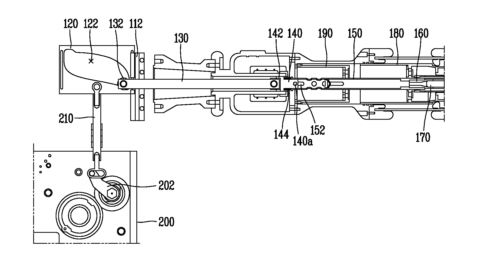
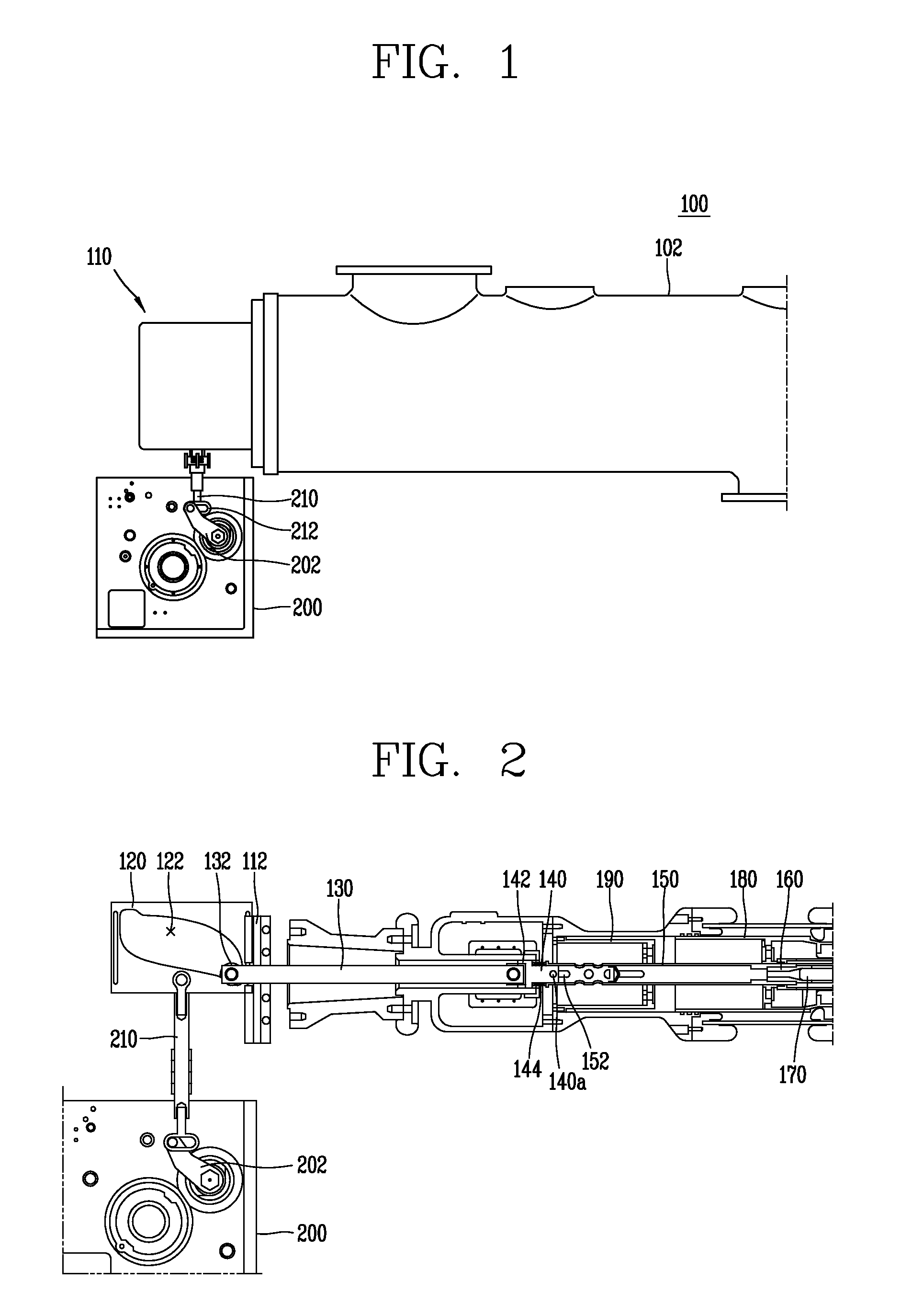
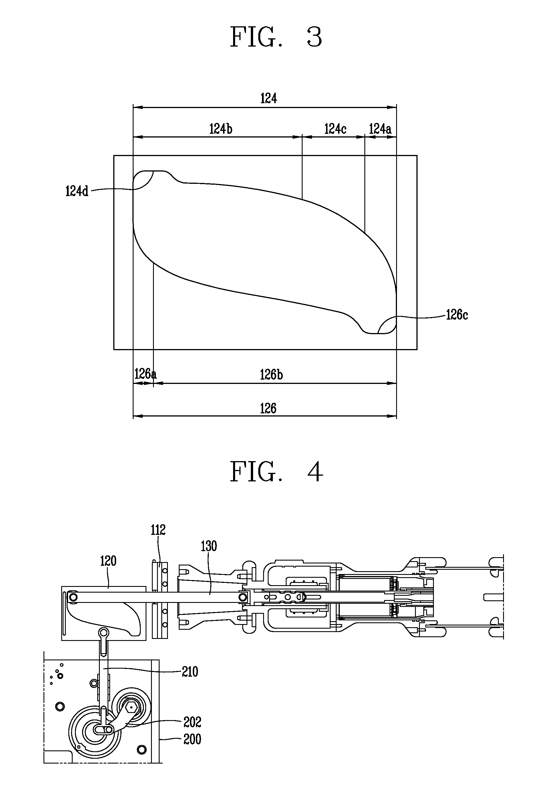
[0040]FIG. 1 is a side view schematically illustrating a portion of the exterior of a gas insulated switchgear according to an exemplary embodiment of the present invention. Referring to FIG. 1, a gas insulated switchgear 100 according to the exemplary embodiment of the present invention includes an enclosure 102 having a substantially cylindrical shape. The interior of the enclosure 102 is charged with a sulfur hexafluoride(abbreviated as SF6 hereinafter) insulating gas, a tasteless, odorless, n...


PUM


Abstract

A gas insulated switchgear includes: an enclosure; a stationary contact arm fixedly installed within the enclosure; a movable contact arm installed to be moved within the enclosure such that it is brought into contact with or separated from the stationary contact arm; a cam reciprocating between closing and opening positions to move the movable contact arm; and an actuator moving the cam, wherein the cam includes first and second cam surfaces, and when the cam moves to an opening position by the actuator, movement acceleration of the movable contact arm by the first cam surface is greater than movement acceleration by the second cam surface and a movement distance of the movable contact arm by the first cam surface is smaller than a movement distance by the second cam surface.

Description

CROSS-REFERENCE TO RELATED APPLICATION[0001]Pursuant to 35 U.S.C. §119(a), this application claims the benefit of earlier filing date and right of priority to Korean Application No. 10-2013-0002233, filed on Jan. 8, 2013, the contents of which is incorporated by reference herein in its entirety.BACKGROUND OF THE INVENTION[0002]1. Field of the Invention[0003]The present disclosure relates to a gas insulated switchgear, and particularly, to a switchgear devised to open or close an electric power transmission line and extinguish an arc generated in performing an insulating or breaking operation by using a gas.[0004]2. Background of the Invention[0005]In general, a switchgear refers to a device that opens or closes an electric load or breaks a current when an accident or a fault such as ground fault, short- circuit, or the like, in a transmission and substation (or transformation) system or in an electrical circuit. In particular a gas insulated switchgear includes a breaking part dispo...

Claims


Application Information

Patent Timeline
IPC IPC(8): H01H33/91
CPCH01H33/91H01H3/42H01H33/42H02B13/035
Inventor YANG, JAE MIN
Owner LSIS CO LTD
Learn More