
Device for separation of oil-water-residue mixture and marking of waste oil

A technology of oil-water mixture and mixture, applied in water/sewage multi-stage treatment, water/sludge/sewage treatment, analysis by chemical reaction of materials, etc. High-efficiency separation of water and slag, low separation purity, etc., to avoid food hygiene and safety problems, complete separation, and simple structure design

Active Publication Date: 2019-06-21
GUIZHOU UNIV
View PDF5 Cites 1 Cited by
  • Summary
  • Abstract
  • Description
  • Claims
  • Application Information

AI Technical Summary

Problems solved by technology

[0003] In recent years, most domestic oil-water slag mixture separation devices have adopted the gravity separation technology in the physical method to separate oil and water. Because of its simple structure, convenient operation, no chemical agents, and no secondary pollution, it has been It is the focus and direction of domestic and foreign scholars' research, but this method only removes slick oil and part of the dispersed oil, the oil content of the treatment liquid far exceeds the national discharge standard and the separation time is long
The separation purity is not high and the separation rate is low, and the oil, water and slag cannot be effectively separated

Method used


Image

  • Device for separation of oil-water-residue mixture and marking of waste oil
  • Device for separation of oil-water-residue mixture and marking of waste oil
  • Device for separation of oil-water-residue mixture and marking of waste oil

Examples


Embodiment Construction

[0020] The present invention will be further described below in conjunction with the accompanying drawings and embodiments, but not as a basis for limiting the present invention.

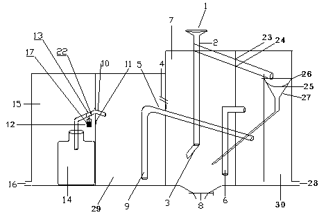
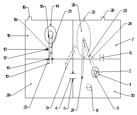
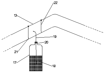
[0021] Embodiment of the present invention: a device for separating oil-water slag mixture and marking waste oil, as attached Figure 1-3 As shown, there are adjacent residue collection chamber 7, waste oil collection chamber 15, oil-water mixture separation chamber 29 and waste water collection chamber 30, wherein the residue collection chamber 7 and waste water collection chamber 30 are located in the middle of the wall A through hole is provided, and a waste water output pipe 6 is penetrated in the through hole to connect the two chambers, and a first oil outlet 4 is arranged on the wall adjacent to the residue collection chamber 7 and the oil-water mixture separation chamber 29 again, through which The first oil outlet 4 connects the two chambers, and the wall adjacent to the waste oil collectio...


PUM


Abstract

The invention discloses a device for separation of an oil-water-residue mixture and marking of waste oil. A residue collection chamber is communicated with a wastewater collection chamber through a wastewater output tube; the residue collection chamber is communicated with an oil-water mixture re-separation chamber through a first oil outlet; a waste oil collection chamber is communicated with theoil-water mixture re-separation chamber through a second oil outlet; an oil conveying tube penetrates through the second oil outlet; an oil collection bucket is arranged in the waste oil collection chamber; one end of the oil conveying tube extends into the oil collection bucket; an oil-water-residue mixture receiving funnel is arranged in the residue collection chamber; the bottom of the oil-water-residue mixture receiving funnel is connected with an oil-water input pipeline; a residue guide screening plate which is arranged in an inclined manner is arranged between the oil-water-residue mixture receiving funnel and the oil-water input pipeline; the tail part of the residue guide screening plate extends into the wastewater collection chamber; a residue collection net bag is arranged below the tail part of the residue guide screening plate. By adopting the device, the oil-water-residue mixture is subjected to solid-liquid separation by using the residue guide screening plate effectively, and secondly, oil and water can be thoroughly separated through density differences of oil and water, siphonic effect, gravitational potential energy and the like.

Description

technical field [0001] The invention relates to a device for separating oil-water slag mixture and marking waste oil, and belongs to the technical field of oil-water separation equipment. Background technique [0002] Although the progress of human civilization has made our lives more convenient, the process of civilization is accompanied by many problems. As global energy demand continues to grow, accidents such as oil spills and industrial oily wastewater discharges occur frequently. This series of accidents caused most of the animals and plants living in the waters near the incident to die, and these toxic components will enter the ecosystem and quickly enter the food chain. These toxic components flow along the food chain from low-level producers to high-level consumers, and finally directly or indirectly affect human health. Therefore, the separation device and technology of the mixture of oil and water slag have attracted more and more attention. At present, the met...

Claims


Application Information

Patent Timeline
IPC IPC(8): C02F9/02G01N21/78
Inventor 高秉婷吴永贵杨开智王晓睿罗杨
Owner GUIZHOU UNIV
Learn More