Rolling-bag tearing device
A rolling bag and hand-tearing technology, which is applied in packaging, winding strips, transportation and packaging, etc., can solve the inconvenient operation, there is no operating device for the rolling bag, and it is difficult to coordinate and cooperate with both hands to tear off the rolling bag And other issues
- Summary
- Abstract
- Description
- Claims
- Application Information
AI Technical Summary
Problems solved by technology
Method used
Image

Examples
Embodiment approach 1
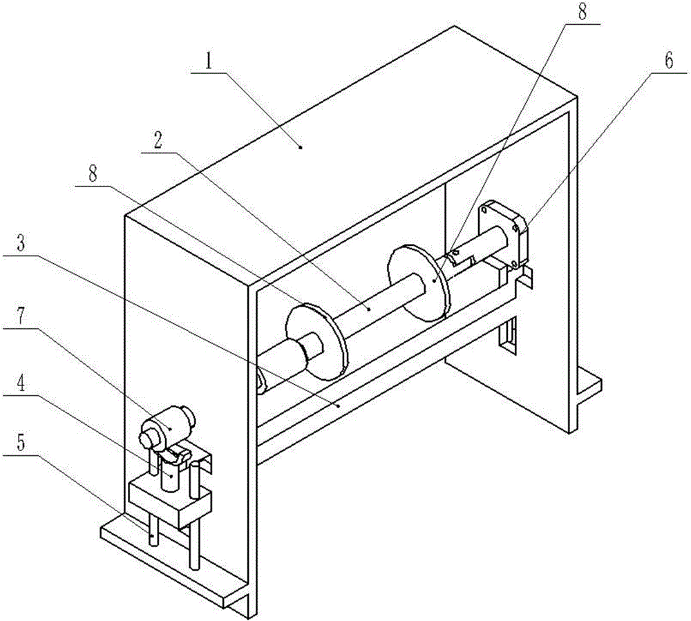
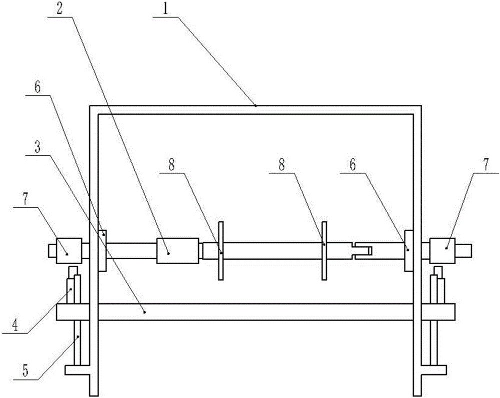
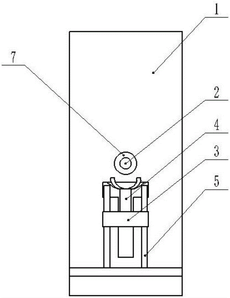
[0039] Combine below figure 1 , 2 , 3, 4, 5, 6, 7, 8, 9, 10, 11, 12, 13, 14, 15, 16, 17 illustrate this embodiment, a hand-tearing device for rolling bags of the present invention consists of a guide rail housing 1 , shaft 2, pull rod 3, block 4, slide rod 5, bearing 6, gear 7 and circular connecting plate 8, which can quickly tear off the roll bag with one hand, and can quickly replace the roll roll bag.
[0040] Both ends of the shaft 2 are rotatably connected to the rail housing 1 through the bearings 6, and the shaft 2 can rotate around its axis. The middle of the shaft 2 is fixedly connected with the circular connecting plate 8, and there are two circular connecting plates 8, and the circular connecting plate 8 is used to fix the rolled bag on the shaft 2, so that the rolled bag When the rolling bag rotates, it can drive the shaft 2 to rotate. The two ends of the shaft 2 are fixedly connected with the gear 7, and the rotation of the shaft 2 will drive the gear 7 to rot...
Embodiment approach 2
[0044] Combine below figure 1 , 2 , 3, 4, 5, 6, 7, 8, 9, 10, 11, 12, 13, 14, 15, 16, and 17 describe this embodiment, and this embodiment is a further description of Embodiment 1.
[0045]The guide rail housing 1 is provided with shaft holes I1-1, shaft holes II1-2, T-shaped guide rails I1-3, T-shaped guide rails II1-4 and slide bar fixing seats 1-5, and the guide rail housing 1 is a door font, the shaft hole I1-1 and shaft hole II1-2 are symmetrically arranged at both ends of the guide rail housing 1, and the T-shaped guide rail I1-3 and T-shaped guide rail II1-4 are symmetrically arranged on the guide rail housing 1; there are two slider fixing seats 1-5 and they are arranged symmetrically at both ends of the guide rail housing 1; the two ends of the shaft 2 are respectively located in the shaft hole I1-1 and the shaft hole II1 -2, the axis of the shaft 2 coincides with the axes of the shaft hole I1-1 and the shaft hole II1-2; The two ends of the pull rod 3 are slidingly ...
Embodiment approach 3
[0047] Combine below figure 1 , 2 .
[0048] The shaft 2 is composed of a first shaft 2-1, a second shaft 2-2, a third shaft 2-3 and a connecting sleeve 2-4; the first shaft 2-1 is a stepped shaft, and the first The big end of the shaft 2-1 is provided with a rectangular block I2-1-1; the second shaft 2-2 is a stepped shaft, and the small end of the second shaft 2-2 is provided with a rectangular block II2-2-1, The big end of the second shaft 2-2 is provided with a connection block 2-2-2, and the connection block 2-2-2 is provided with a cylindrical hole I2-2-2-1; the third shaft 2-2- 3 is a stepped shaft, the big end of the third shaft 2-3 is provided with a connecting cavity 2-3-1, and the connecting cavity 2-3-1 is provided with a cylindrical hole II 2-3-1-1; The connection sleeve 2-4 is provided with a rectangular cavity 2-4-1 and a circular through hole 2-4-2 inside; the first shaft 2-1 and the second shaft 2-2 pass through the connection sleeve 2- 4 Fixed connection,...
PUM
 Abstract
Description
Claims
Application Information
 - R&D Engineer
- R&D Manager
- IP Professional
- Industry Leading Data Capabilities
- Powerful AI technology
- Patent DNA Extraction
Browse by: Latest US Patents, China's latest patents, Technical Efficacy Thesaurus, Application Domain, Technology Topic.
© 2024 PatSnap. All rights reserved.Legal|Privacy policy|Modern Slavery Act Transparency Statement|Sitemap