
A method for anti-floating of the core mold of the cup mouth column foundation

A technology of cup mouth foundation and column foundation, which is applied in the anti-floating field of cup mouth column foundation mandrel, can solve the problems of inconvenient construction method of cup mouth column foundation mandrel, inability to meet the installation of factory building columns, and the elevation of the bottom of cup mouth, etc., so as to avoid The effect of secondary cleaning work, installation accuracy assurance, and production efficiency improvement

Active Publication Date: 2019-06-14
MCC5 GROUP CORP SHANGHAI
View PDF4 Cites 0 Cited by
  • Summary
  • Abstract
  • Description
  • Claims
  • Application Information

AI Technical Summary

Problems solved by technology

[0002] In the construction of construction projects, cup-mouth column foundations are often encountered, especially in industrial plant construction, where more cup-mouth column foundations are used for factory buildings. During the construction of cup-mouth column foundations, the cup-mouth mandrels will During pouring, due to the side pressure of the concrete, the elevation of the bottom of the cup mouth is higher than the design requirement, which cannot meet the installation of the plant column. It needs to be chiseled out, which is time-consuming and labor-intensive, and affects the installation quality.
[0003] Therefore there are above-mentioned inconveniences and problems in the known cup mouth column foundation mandrel construction mode

Method used


Image

  • A method for anti-floating of the core mold of the cup mouth column foundation
  • A method for anti-floating of the core mold of the cup mouth column foundation
  • A method for anti-floating of the core mold of the cup mouth column foundation

Examples


Embodiment 1

[0024] The method for anti-floating of the core mold of the cup mouth column foundation of the present invention comprises the following steps:

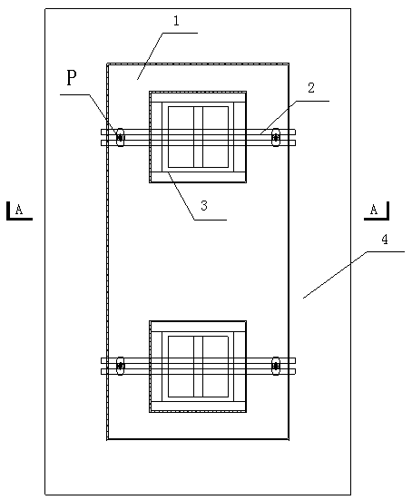
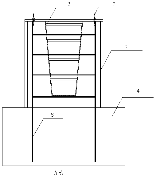
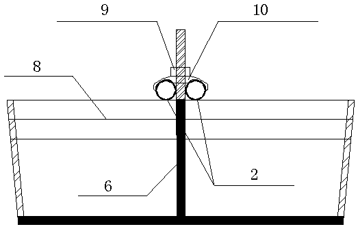
[0025] see now Figure 1-Figure 3 , figure 1 It is a schematic diagram of anti-floating of the core mold of the cup mouth column foundation in the embodiment of the present invention, figure 2 for figure 1 Middle A-A sectional view, image 3 for figure 1 Enlarged view of the middle P site. a. Retain tie bars 6: When the steel bars of the column foundation cap 4 are installed, a tie bar with the same specification and size as the column base cup mouth steel bar is left in the center of the side line corresponding to the column base cup mouth 1 6.

[0026] b. Welding bolt head: After pouring concrete for the cap of the column foundation, install the foundation reinforcement of the cup mouth, support the cup mouth mandrel and the cup mouth side mold, and weld and fix a section of 200mm long full thread on the top of the two tie b...


PUM


Abstract

The invention provides an anti-floating method for a foundation core mold of a cup-mouth column. The anti-floating method is characterized by comprising the following steps that a, tie bars (6) are reserved; b, bolt heads are welded; c, press rods are mounted; and d, concrete pouring is conducted on the cup-mouth column, specifically, after the work from the step a to the step c is completed, cup-mouth base concrete is poured, the foundation core mold of the cup-mouth column cannot float under the tension of the tie bars (6) and the pressure of the press rods, and an anti-floating structure is formed so as to ensure that the elevation of concrete pouring at the bottom of the cup-mouth does not change. The anti-floating method has the advantages that cup-mouth bars are utilized to serve as the tie bars, a split rod set is utilized to serve as threaded heads of the tie bars, steel pipes are utilized to serve as the press rods, 3-shaped clamps and split rod nuts are utilized to conduct screwing fixing, the materials are utilized locally, operation can be conducted without the need of professional personnel, unnecessary roughing processing can be reduced by utilizing an anti-floating body, secondary cleaning work is avoided, the production efficiency is improved, the construction cost is saved, operation is simple and the mounting precision is ensured.

Description

technical field [0001] The invention relates to an anti-floating method for a foundation mandrel in civil structure construction, in particular to a method for anti-floating of a cup mouth column foundation mandrel. Background technique [0002] In the construction of construction projects, cup-mouth column foundations are often encountered, especially in industrial plant construction, where more cup-mouth column foundations are used for factory buildings. During the construction of cup-mouth column foundations, the cup-mouth mandrels will During pouring, due to the side pressure of the concrete, the elevation of the bottom of the cup is higher than the design requirement, which cannot meet the installation of the plant column, and needs to be chiseled out, which is time-consuming and labor-intensive, which affects the installation quality. [0003] Therefore there are above-mentioned inconveniences and problems in the known cup mouth column foundation mandrel construction m...

Claims


Application Information

Patent Timeline
Patent Type & Authority Patents(China)
IPC IPC(8): E02D27/42E02D31/12
CPCE02D27/42E02D31/12
Inventor 邱战武
Owner MCC5 GROUP CORP SHANGHAI
Learn More