

Heater and image forming apparatus
A heater and heat-generating area technology, applied in the direction of electric recording technology using charge pattern, instrument, equipment of electric recording process using charge pattern, etc., can solve the problem of poor fixing quality and achieve the suppression of uneven temperature distribution Effect
- Summary
- Abstract
- Description
- Claims
- Application Information
AI Technical Summary
Problems solved by technology
Method used
Image

Examples
no. 1 approach
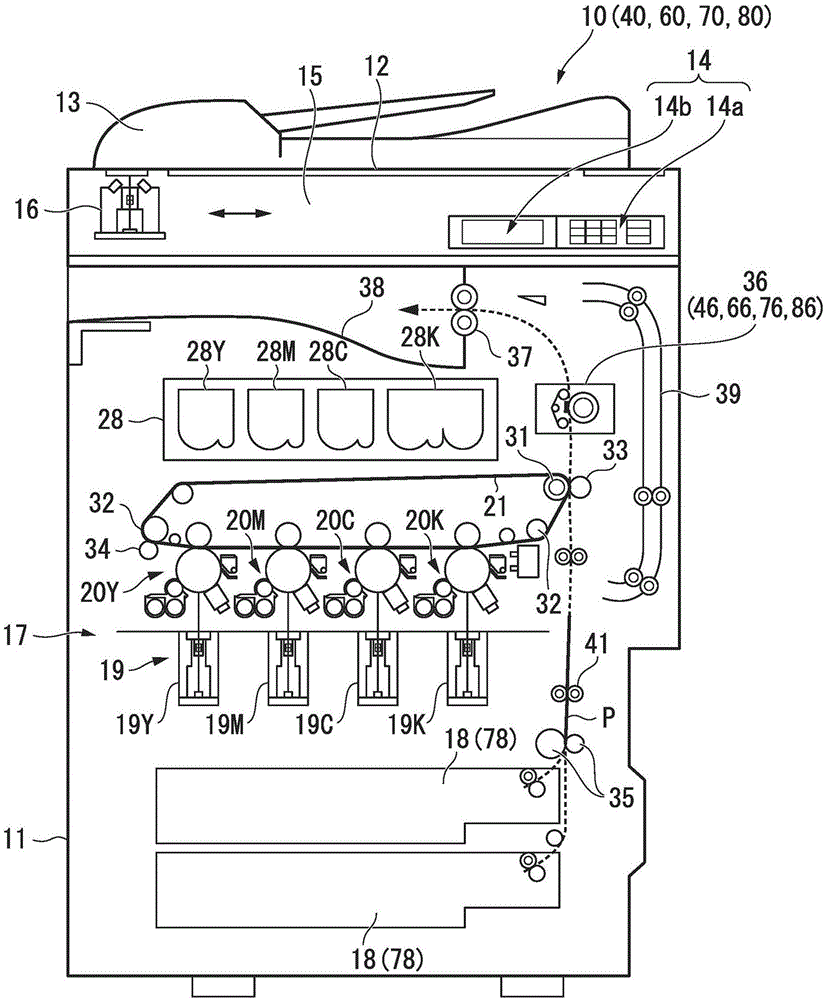
[0030] figure 1 It is a schematic cross-sectional view showing a configuration example of the image forming apparatus according to the first embodiment. exist figure 1 In , the size and shape of each component are exaggerated or simplified for easy viewing (the same applies to the following drawings).
[0031] figure 1 The image forming apparatus 10 of the first embodiment shown is, for example, an MFP (Multi-Function Peripherals, multi-function peripherals), a printer, a copier, etc., which are multi-function machines. In the following description, an MFP will be described as an example.
[0032] On an upper portion of a main body 11 of the image forming apparatus 10, a document table 12 made of transparent glass is provided. An automatic document feeder (ADF) 13 is provided on the document table 12 . An operation panel 14 is provided on an upper portion of the main body 11 . The operation panel 14 has an operation panel 14 a having various keys and a touch panel displa...
no. 2 approach
[0232] The heater of the second embodiment and a fixing device using the heater will be described.
[0233] Figure 11 It is a block diagram showing a configuration example of the control system of the image forming apparatus according to the second embodiment. Figure 12 It is a schematic cross-sectional view in the longitudinal direction showing a structural example of the heating member 461 of the second embodiment. Figure 13 It is a schematic plan view showing a structural example of the heating member 461 according to the second embodiment. But when Figure 13 In , the illustration of the surface protection layer 361d is omitted for ease of observation.
[0234] Such as figure 1 As shown, the image forming apparatus 40 of the second embodiment has a fixing device 46 instead of the fixing device 36 of the image forming apparatus 10 of the first embodiment described above. Such as Figure 11 As shown, the image forming apparatus 40 has a control system 51 instead of ...
no. 3 approach
[0311] The heater of the third embodiment and a fixing device using the heater will be described.
[0312] Figure 15 It is a schematic cross-sectional view showing a structural example of a main part of the heater according to the third embodiment.
[0313] Such as Figure 15 As shown, the fixing device 56 has a heating film 563 and a heating member 561 as a heater of this embodiment instead of the fixing belt 363 and the heating member 361 of the fixing device 36 in the first embodiment described above. In the fixing device 56 , the belt transport roller 364 and the tension roller 365 of the fixing device 36 in the first embodiment described above are removed.
[0314] The fixing device 56 also has a heater holder 562 .
[0315] The following description will focus on points different from the first embodiment described above.
[0316] The heating film 563 is a cylindrical member that rotates in conjunction with the rotation of the pressure roller 366 . The heating film...
PUM
 Abstract
Description
Claims
Application Information