Antenna switching method and device and mobile terminal
An antenna switching and antenna technology, applied in the direction of antenna support/installation device, antenna, antenna parts, etc.
- Summary
- Abstract
- Description
- Claims
- Application Information
AI Technical Summary
Problems solved by technology
Method used
Image

Examples
no. 1 example
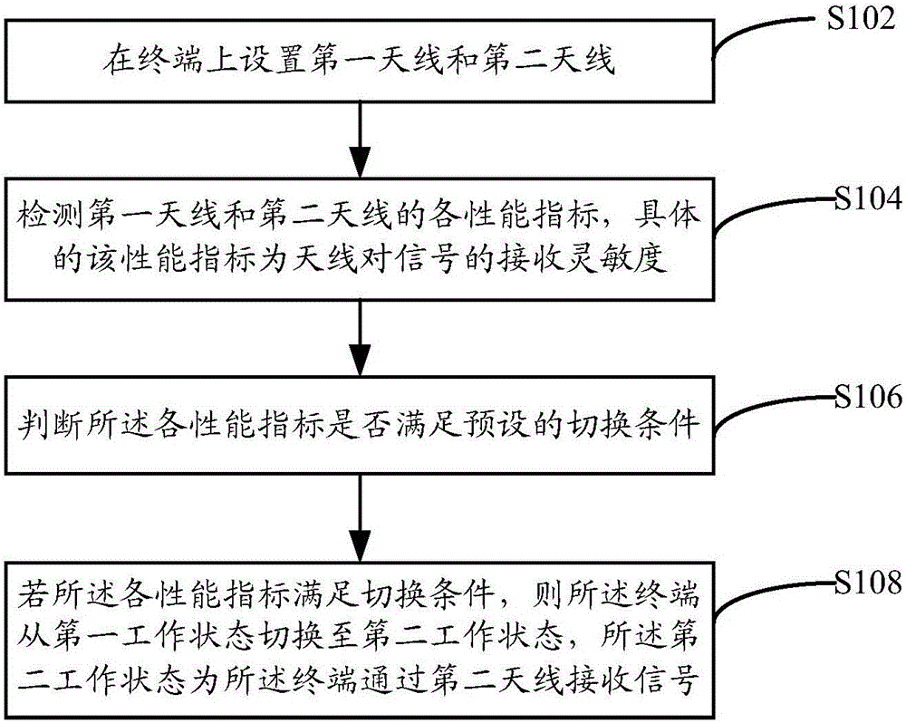
[0024] See figure 1 , figure 1 It is a flow chart of the antenna switching method provided by the embodiment of the present invention. In this embodiment, the antenna switching method specifically includes the following steps:
[0025] S102. Set the first antenna and the second antenna on the terminal.
[0026] In this step, when setting the antenna for the terminal, the first antenna is used as the working antenna in the first working state, and the second antenna is used as a spare antenna for receiving signals in the second working state, and the working antenna is specifically set as Omni-directional antenna, the first working state here refers to the state in which the first antenna of the terminal receives external signals through the first antenna when it is not disturbed; when the terminal is in the second working state, the terminal can switch to the second antenna Signals are received, and the second antenna may be set as a directional antenna, where the second wo...
no. 2 example
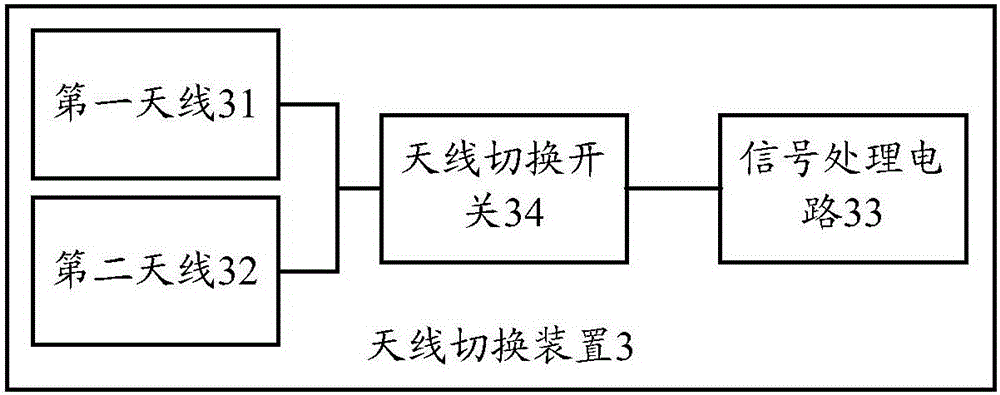
[0049] Please refer to image 3 , image 3 A schematic structural diagram of the antenna switching device provided in this embodiment, as shown in image 3 As shown, the antenna switching device 3 provided in this embodiment includes: a first antenna 31, a second antenna 32, a signal processing circuit 33 and an antenna switching switch 34, and two antennas are set inside the terminal, wherein in the first working state Next, the terminal receives signals through the first antenna, and the second antenna serves as a backup antenna, wherein:
[0050] The first antenna 31 and the second antenna 32 are used to receive signals. In the first working state, the signal processing circuit 33 receives signals through the first antenna. In the second working state, the terminal receives signals through the second antenna. ;
[0051] The signal processing circuit 33 is used to control the first antenna 31 and the second antenna 32 to receive signals, and detect the performance indicat...
no. 3 example
[0060] Please refer to Figure 4 , Figure 4 The circuit structure diagram of the antenna switching device provided by the embodiment of the present invention.
[0061] The antenna switching device 3 provided in this embodiment includes two antennas, the antenna 41 is a first antenna, the antenna 42 is a spare antenna, a double pole double throw switch 43, a multiplexer 44, a comparator 45, a radio frequency integrated circuit 46, and Signal conditioner 47, wherein, antenna switching device 3 selects antenna 41 or antenna 42 to receive external signals through double-pole double-throw switch 43, then performs signal processing through multiplexer 44, and sends it to radio frequency integrated circuit 46 after processing is completed. The radio frequency integrated circuit 46 detects the receiving sensitivity of the antenna 41 and the antenna 42 to the signal according to the signal sent by the multiplexer 44, and the signal modulator 47 obtains the receiving sensitivity of th...
PUM
 Abstract
Description
Claims
Application Information
 - R&D
- Intellectual Property
- Life Sciences
- Materials
- Tech Scout
- Unparalleled Data Quality
- Higher Quality Content
- 60% Fewer Hallucinations
Browse by: Latest US Patents, China's latest patents, Technical Efficacy Thesaurus, Application Domain, Technology Topic, Popular Technical Reports.
© 2025 PatSnap. All rights reserved.Legal|Privacy policy|Modern Slavery Act Transparency Statement|Sitemap|About US| Contact US: help@patsnap.com