Eureka AIR delivers breakthrough ideas for toughest innovation challenges, trusted by R&D personnel around the world.

Bar-type screen cage

A sieve cage and strip technology, applied in the direction of filter screen, fixed filter element filter, grille, etc., can solve the problems of high cost, difficult to reliable groove width, etc., and achieve the effect of durable connection, high stability and durability

Inactive Publication Date: 2018-01-02
ANDRITZ FIEDLER GMBH & CO KG
View PDF11 Cites 1 Cited by
  • Summary
  • Abstract
  • Description
  • Claims
  • Application Information

AI Technical Summary

Problems solved by technology

[0006] All currently known configurations of bar screen cages are very cost-intensive and it is particularly difficult to reliably reproduce a predetermined slot width

Method used


Image

  • Bar-type screen cage
  • Bar-type screen cage
  • Bar-type screen cage

Examples


Embodiment Construction

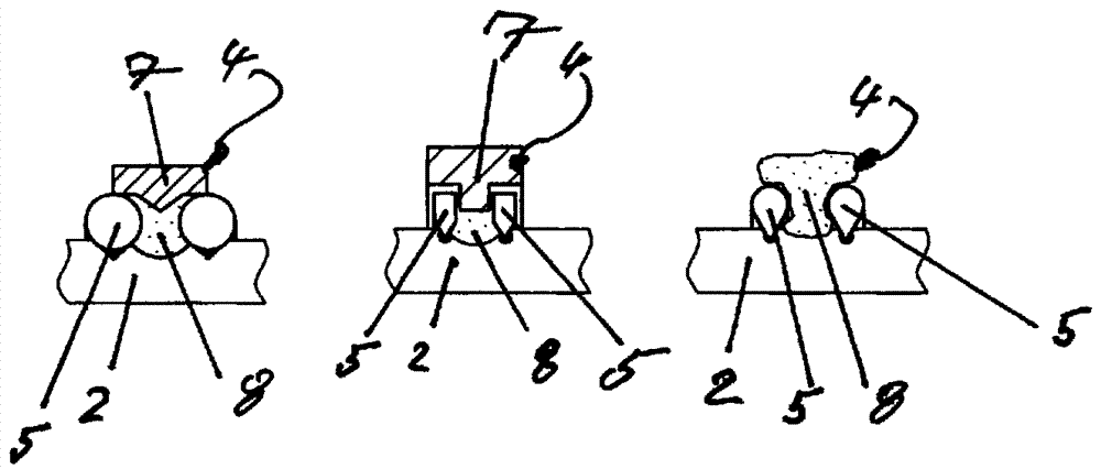
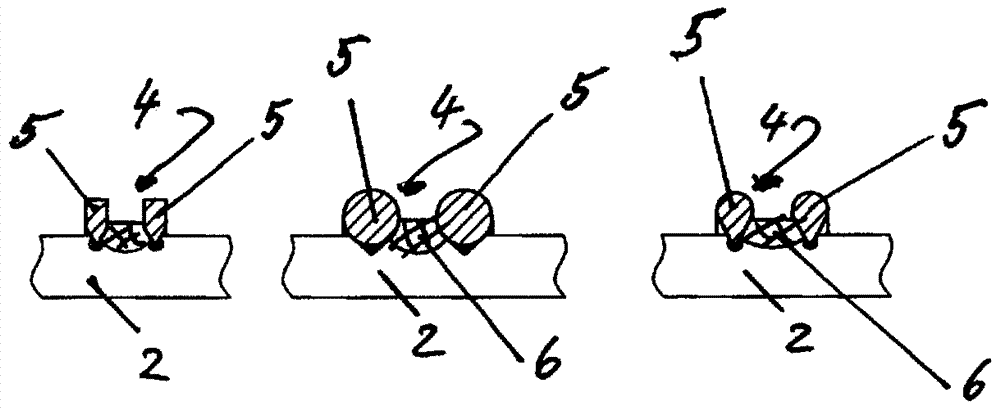
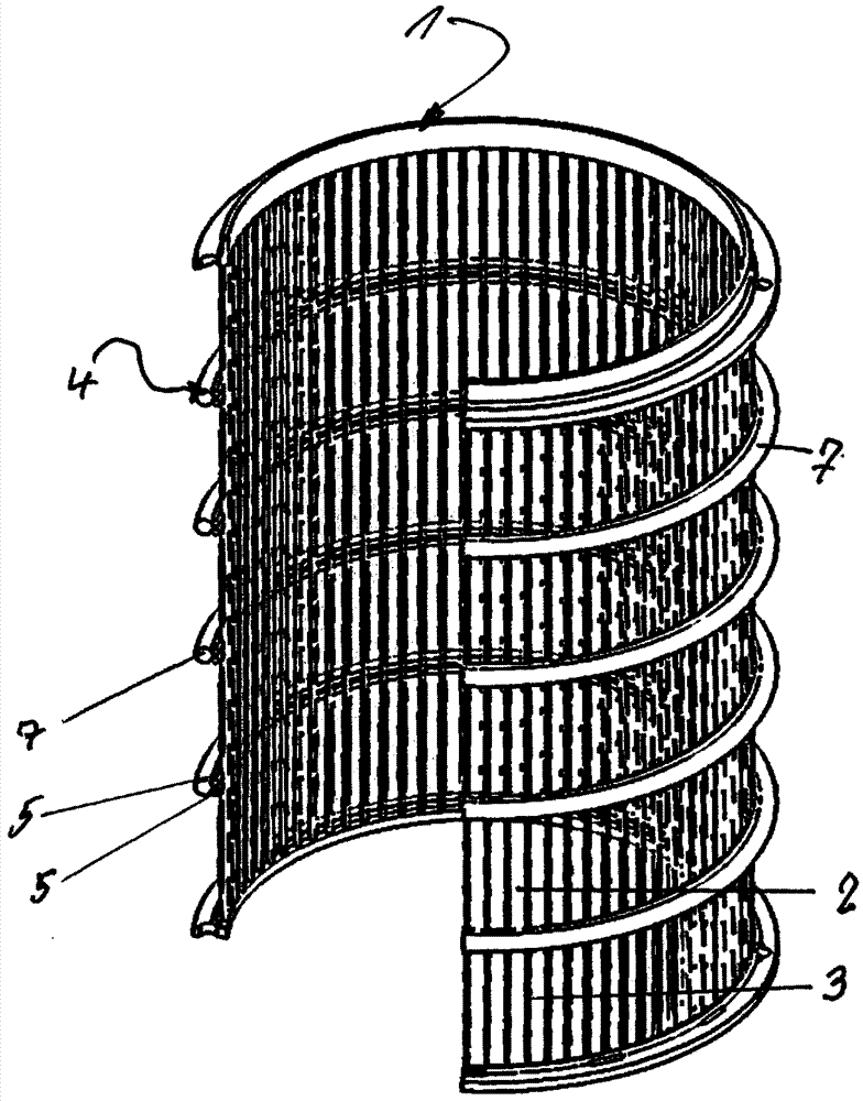
[0024] figure 1 with 2 Shown is a screen cage, generally indicated with reference number 1 , having circumferentially spaced profiled bars (profile bars) 2 with screen slots 3 with predetermined openings delimited between the bars. Slot width. The screen cage 1 also comprises a plurality of support arrangements indicated with reference numeral 4, spaced apart in the axial direction of the screen cage 1 and fastened on the outside of the screen bars 2 by means of welding. as in as figure 1 with 2 The perspective view of the enlarged cross-sectional view of image 3 As can be particularly seen in , each support arrangement 4 comprises at least two support wires 5 spaced apart in the axial direction of the bar 2 . These support wires 5 are fastened to the bars by means of resistance welding. An additional weld seam, indicated with reference numeral 6 , is provided, which fixedly connects the two support wires 5 of each support arrangement 4 with the profile bar or profile b...


PUM


Abstract

A bar-type screen cage (1) is specified which has profiled screen bars or profile bars (2) which are spaced apart in a circumferential direction. Multiple support arrangements (4) which are spaced apart in an axial direction of the screen cage (1) are fastened by welding to the profile bars or screen bars (2) at the outside. The screen bars (2), which are spaced apart in an axial direction, form screen slots (3) between them. Each support arrangement (4) comprises at least two support wires (5) which are closely spaced apart in the axial direction of the screen bars and which are fixed to thescreen bars (2) by resistance welding. The two support wires (5) of each support arrangement (4) and the profile bars (2) are fixedly connected to one another by way of an additional weld seam (6). Itis preferably possible for a reinforcement ring (7) to be provided on the outer side on each support arrangement (4), which reinforcement ring preferably interacts in positively locking fashion withthe respective support arrangement (4), the support wires (5) and the profile bars (2). If appropriate, the bar-type screen cage (1) may comprise a support casing (back-up casing) (10) at the outside.

Description

technical field [0001] The invention relates to a bar screen cage with profiled bars (profile bars) spaced apart in the circumferential direction to form screen troughs, wherein a plurality of supports spaced apart in the axial direction on the outside are arranged The structure is fastened by means of welding, the support arrangement may eg be formed by support wires or support rings. Such a bar screen cage is known from WO 02 / 097 190 A1. Background technique [0002] From EP 0 958 432 B1 wire screen products (Drahtsiebprodukt), such as screen plates or screen cages, are known, which are resistance-welded screen structures. In this case, the support wire is constructed with two extensions in order to introduce high current densities, its leading edge deforms, melts and fixes the arrangement of forming screen cage and support wire in two spaced apart defined welds. point. This is intended to improve stability and in particular bending stability. [0003] A screen cage co...

Claims


Application Information

Patent Timeline
Patent Type & Authority Applications(China)
IPC IPC(8): B01D29/11B01D29/35B01D29/44B07B1/18B07B1/46D21D5/16
CPCB01D29/111B01D29/35B01D29/445B07B1/18B07B1/4618B07B1/469D21D5/16
Inventor T.米科拉特M.赖因斯坦
Owner ANDRITZ FIEDLER GMBH & CO KG
Why Eureka
Eureka Blog
Learn More