Gear making method for tooth finishing and its combination tool

A technology of combining cutting tools and cutting tools, applied in the direction of gear tooth manufacturing tools, manufacturing tools, components with teeth, etc., can solve the problem of increasing machining errors

Active Publication Date: 2021-05-11
PROFILATOR
View PDF10 Cites 0 Cited by
  • Summary
  • Abstract
  • Description
  • Claims
  • Application Information

AI Technical Summary

Problems solved by technology

[0007] The rotational movement errors of the two tools and the fastening of the workpiece can unfavorably add up
This increases the processing error

Method used


Image

  • Gear making method for tooth finishing and its combination tool
  • Gear making method for tooth finishing and its combination tool
  • Gear making method for tooth finishing and its combination tool

Examples


Embodiment Construction

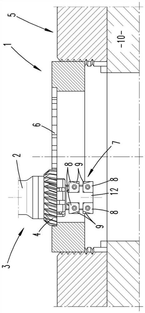
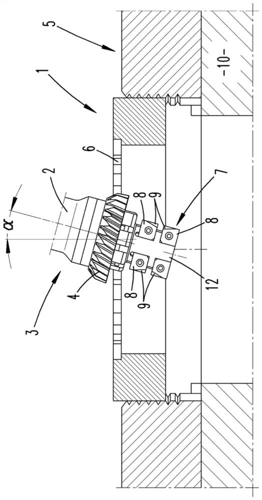
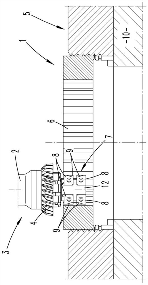
[0019] exist Figures 4 to 6 The combination tool 3 shown in has a clamping end 11, by means of which the combination tool 3 can be clamped in the chuck of the tool shaft 2, which can be driven in rotation by an electric motor. The motor is controlled by the controller. The controller also controls another motor for driving the workpiece axis 5 . The workpiece shaft 5 has a chuck 10, and the wheel blank 1 to be processed is clamped in the chuck 10. The controller is designed to drive the tool shaft 2 and the workpiece shaft 5 in synchronous rotation relative to each other.

[0020] The combination tool 3 has a skiving gear 4 with which an internal toothing 6 can be produced by hobbing a wheel blank as a blank, as described in DE 10 2008 037 514 A1. For this purpose, the tool shaft 2 and the workpiece shaft 5 are driven to rotate synchronously with one another in such a way that the cutting teeth of the scraper gear 4 scrape into the tooth spaces formed by the gear teeth 6 ....


PUM


Abstract

The invention relates to a gear manufacturing method in which, in a first step, a scraper gear (4) driven in rotation by a tool shaft (2) is used on a wheel blank (1) driven in rotation by a workpiece shaft (5) machining of gear teeth (6), where the axis of the workpiece axis (5) and the axis of the tool axis (2) form an intersection angle (α) and the feed is carried out in the direction of extension of the tooth flank, and wherein, in a second step, At least some teeth of the gear teeth (6) are machined with a tooth machining tool (7). A combination tool is used, wherein the tooth processing tool (7) and the scraping gear (4) are fixedly connected to each other. Between these two steps, the combined tool (3) remains connected to the tool shaft (2) and the wheel blank (1) to the workpiece shaft (5). Only the relative position of the tool axis (2) relative to the workpiece axis (5) and the rotational speed ratio of the two axes (2, 5) are changed between these two steps.

Description

technical field [0001] The invention relates to a gear manufacturing method, wherein, in a first step, gear teeth are machined in a wheel blank driven to rotate synchronously by a workpiece shaft with a skiving gear driven in rotation by a tool shaft, where the workpiece shaft and the tool The axes of the shafts intersect each other at an angle and the feed is carried out in the direction of extension of the tooth flanks, and wherein, in a second step, at least some teeth of the gear tooth are machined with a tooth machining tool. Background technique [0002] DE102008037514A1 describes a method for the production of gears from wheel blanks. Blanks can be toothed internally or externally with hobbed gears. For this purpose, the wheel blank is fastened on the workpiece shaft and the skiving gear is fastened on the tool shaft. Drives the workpiece shaft and the tool shaft to rotate synchronously. The axis of the workpiece shaft and the axis of the tool shaft form a crossing...

Claims


Application Information

Patent Timeline
Patent Type & Authority Patents(China)
IPC IPC(8): B23F21/00B23F23/12B23F5/16B23F19/10B23P13/02B23F17/00B23P15/14
CPCB23F5/163B23F17/006B23F19/107B23F21/005B23F23/1237B23P13/02B23P15/14Y10T29/5168Y10T29/5176Y10T409/101272Y10T409/105565Y10T409/10795Y10T409/108586
Inventor S.海恩
Owner PROFILATOR
Why Eureka
Try Eureka