Variable speed pulley and bicycle driving device with the same

A technology of variable speed belts and pulleys, which is applied in chain/belt transmissions, vehicle gearboxes, vehicle components, etc., and can solve problems such as the separation distance and change of difficult two pulley pieces

Inactive Publication Date: 2011-04-27
MITSUBOSHI BELTING LTD
View PDF4 Cites 0 Cited by
  • Summary
  • Abstract
  • Description
  • Claims
  • Application Information

AI Technical Summary

Problems solved by technology

[0006] However, in the transmission pulley described in Patent Document 1, the fixed sheave piece is fixed to the hub, and only the movable sheave piece is moved to change the separation distance between the two sheave pieces. Separation distance of sheets changes smoothly

Method used


Image

  • Variable speed pulley and bicycle driving device with the same
  • Variable speed pulley and bicycle driving device with the same
  • Variable speed pulley and bicycle driving device with the same

Examples


no. 1 approach

[0067] Hereinafter, a first embodiment of the present invention will be described.

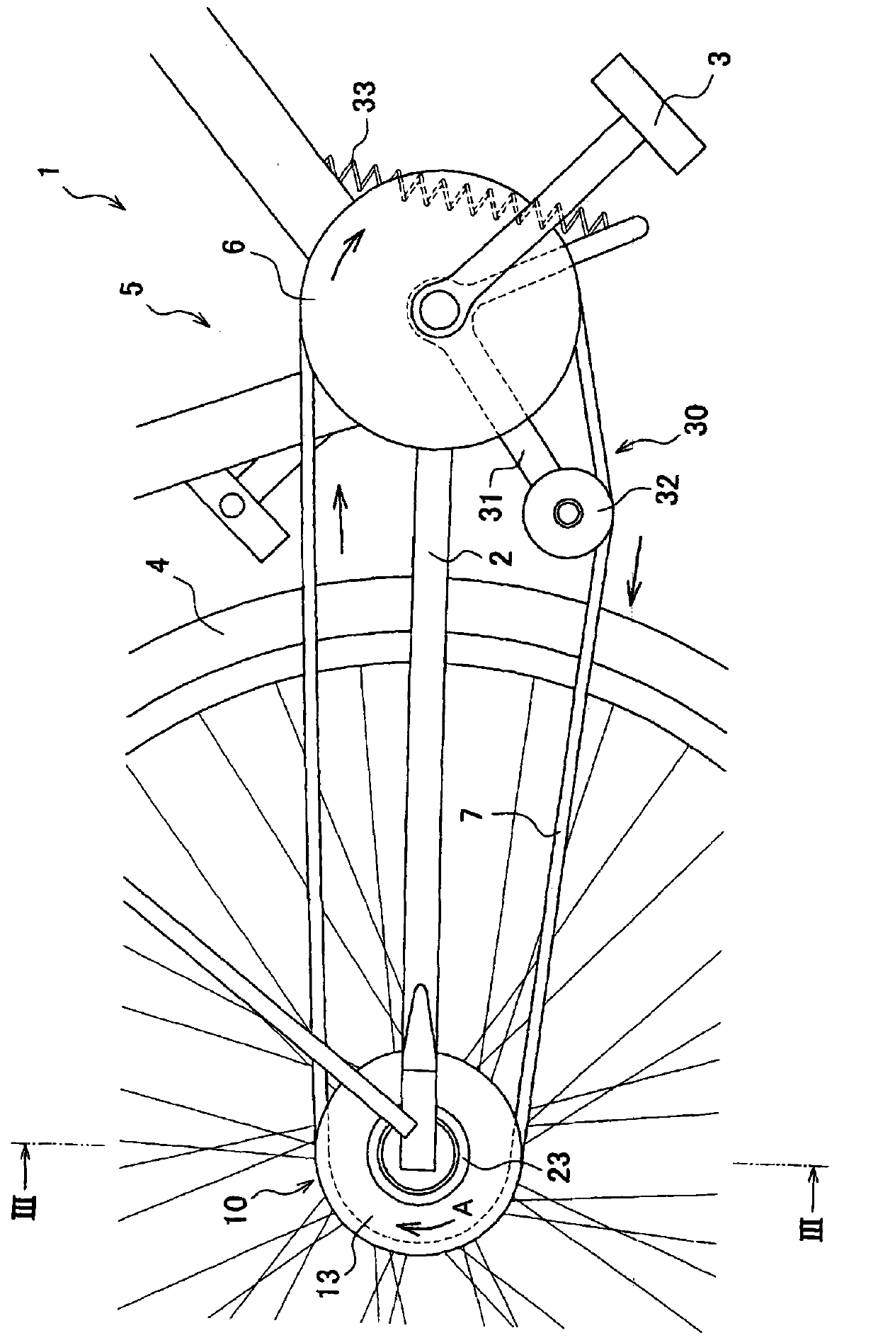
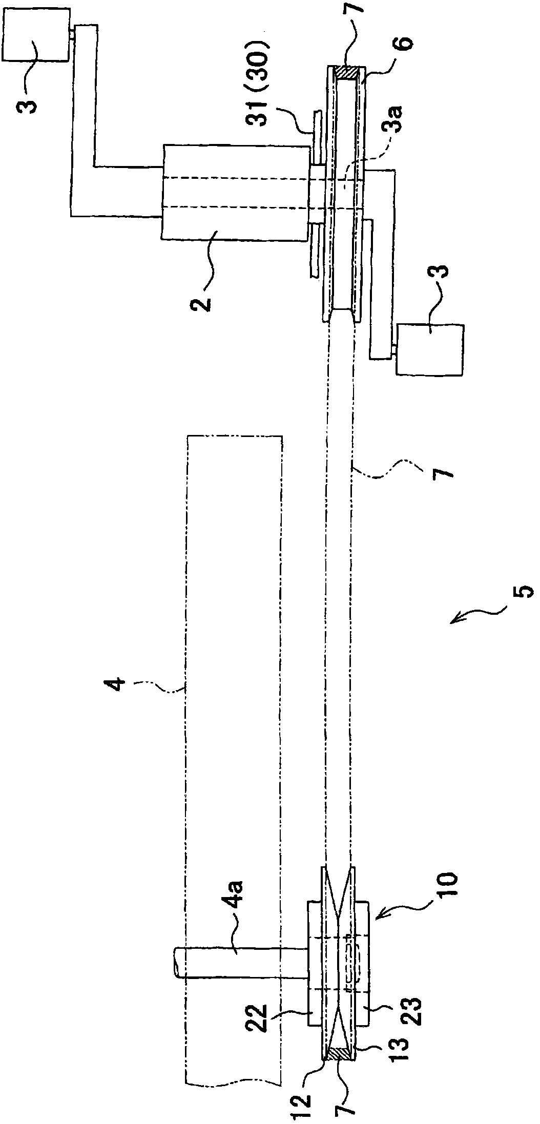
[0068] The bicycle drive device 5 of this embodiment is applied to the bicycle 1 . Such as figure 1 as well as figure 2 As shown, a bicycle 1 has a frame 2 , pedals 3 , wheels (rear wheels) 4 , and a bicycle drive device 5 that transmits rotation of the pedals 3 to the wheels 4 . Rotary shaft 3a of pedal 3 (refer to figure 2 ) and the rotation axis 4a of the wheel 4 (refer to figure 2 ) are respectively freely rotatably mounted on the frame 2.

[0069] The bicycle driving device 5 has: a driving pulley 6 connected to the rotation shaft 3a of the pedal 3; a wheel pulley (speed change pulley) 10 connected to the rotation shaft 4a of the wheel 4; On the drive pulley 6 and the wheel pulley 10 ; and the slack side tension maintaining device 30 .

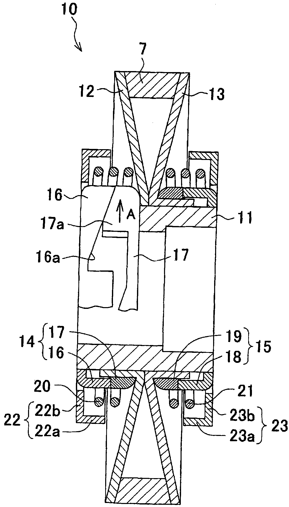
[0070] Such as image 3 As shown, the tire 7 is a so-called V-shaped tire having a V-shaped cross section whose width becomes narrower toward t...

no. 2 approach

[0106] Next, a second embodiment of the present invention will be described. However, the same symbols are attached to the same structures as those in the first embodiment, and descriptions thereof are appropriately omitted. The structure of the wheel pulley (speed change pulley) of the bicycle drive device according to this embodiment is different from that of the first embodiment, and the other structures are the same as those of the first embodiment.

[0107] Such as Figure 8 As shown, the wheel pulley 110 of this embodiment has a hub 11, two pulley pieces 112, 113, two torque cams 114, 115, two torsion coil springs (urging devices) 20, 21, and two Spring covers 22,23.

[0108] The two pulley pieces 112 and 113 are respectively formed of conical annular members, and are attached to the hub 11 so as to be movable in the axial direction and the circumferential direction via torque cam pieces 117 and 119 to be described later.

[0109] 2 torque cams 114,115 are arranged on...

no. 3 approach

[0121] Next, a third embodiment of the present invention will be described. In addition, the same code|symbol is attached|subjected to the same structure as said 1st Embodiment or 2nd Embodiment, and the description is abbreviate|omitted suitably. The structure of the wheel pulley (speed change pulley) of the bicycle drive device according to this embodiment is different from that of the first embodiment, and the other structures are the same as those of the first embodiment.

[0122] Such as Figure 9 As shown, the wheel pulley 210 of this embodiment is constituted by the hub 11 , two pulley pieces 112 , 113 , and two torque cams 114 , 115 . The wheel pulley 210 has the same structure as the wheel pulley 110 of the second embodiment except that the two torsion coil springs 20 and 21 and the two spring covers 22 and 23 are not provided.

[0123] In this wheel pulley 10, when the pull force of the pulley belt 7 is small, the relative rotational force of the hub 11 with respec...


PUM


Abstract

The present invention provides a variable speed pulley which can cause smooth change of separation distance of two pulley pieces and a bicycle driving device with the same. The variable speed pulley (10) is provided with the following components: a cylindrical hub (11) connected with a rotating a rotating shaft, two pulley sheets (12,13), two torque cams (14,15), and two force applying devices (20,21). The two pulley sheets are respectively equipped on the outer peripheral part of the hub. A V groove for keeping a wheel belt with a V-shaped section is formed between two opposite surfaces of the pulley sheets. Two torque cams are respectively set on the two cam sheets. Each torque cam is composed of two torque cam sheets (16,17(18,19)) which can movably fasten in a spiral direction and are respectively fixed on the hub and the pulley sheets (12(13)). The force applying devices are respectively provided on the two pulley sheets (12,13) and apply force to the pulley sheets (12,13) in a direction of separating the two pulley sheets.

Description

technical field [0001] The present invention relates to a speed change pulley and a bicycle drive device using the speed change pulley. Background technique [0002] Conventionally, there are known speed change pulleys that change the winding diameter of the sheave in order to change the rotational speed ratio to transmit rotational power. [0003] For example, the speed change pulley described in Patent Document 1 has a cylindrical hub fixed to the rotating shaft, a fixed sheave fixed to the hub, and a movable sheave slidably mounted on the hub. Between the movable sheave and the fixed sheave, a belt having a V-shaped cross section; a torque cam; and a compression coil spring biasing the movable sheave toward the fixed sheave are sandwiched. The torque cam has: a cylindrical body formed with a cam groove extending in a helical direction and fixed to the movable sheave; and a cam pin protrudingly provided on the hub and inserted into the cam groove . When the movable shea...

Claims


Application Information

Patent Timeline
Patent Type & Authority Applications(China)
IPC IPC(8): B62M9/04
Inventor 长谷川新桥本康弘森山和也磯江俊介
Owner MITSUBOSHI BELTING LTD
Why Eureka
Try Eureka