Scissor arm assembly for a scissor lift of aerial work platform

A technology of working platform and lifting mechanism, applied in the direction of lifting frame, lifting device, etc., can solve the problems of weakened beams, scissor beams, complex manufacturing, and difficult parts accuracy

Active Publication Date: 2018-01-02
HAULOTTE GROUP
View PDF6 Cites 1 Cited by
  • Summary
  • Abstract
  • Description
  • Claims
  • Application Information

AI Technical Summary

Problems solved by technology

This solution may create difficulties with the accuracy of the parts
In addition, this solution also requires the placement of spacers in the beam receiving the bushing, which further complicates the manufacture of scissor beams
It is also necessary to create holes in the tubular beams for the introduction of spacers therein, which weakens the beams

Method used


Image

  • Scissor arm assembly for a scissor lift of aerial work platform
  • Scissor arm assembly for a scissor lift of aerial work platform
  • Scissor arm assembly for a scissor lift of aerial work platform

Examples


Embodiment Construction

[0064] The following will refer to Figure 6 to Figure 15 Preferred embodiments of the present invention are described.

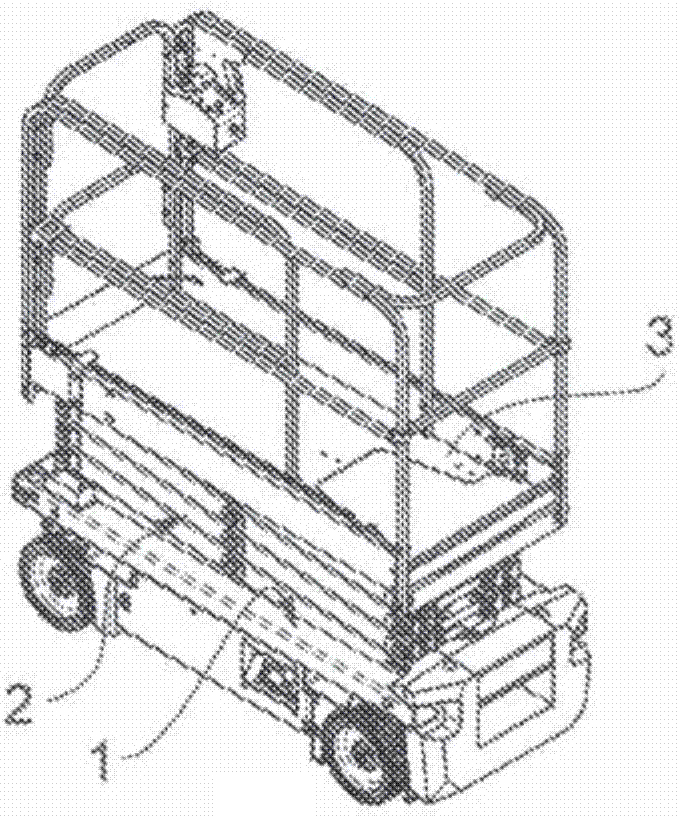
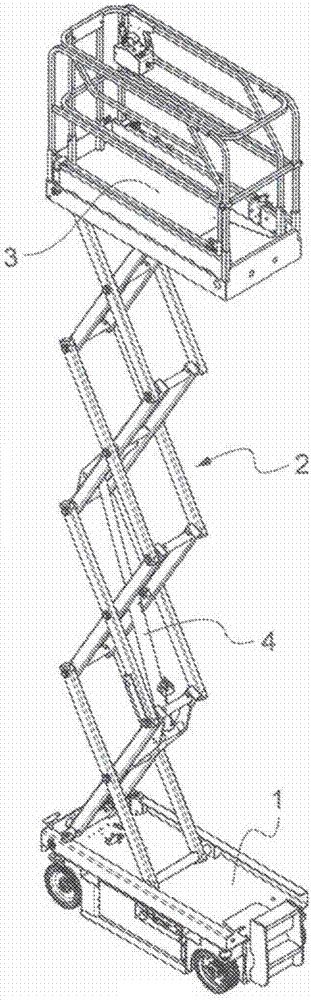
[0065] Figure 6 shows the setting as an alternative to the figure 1 and figure 2 of aerial work platforms image 3 An overall view of the scissor lift mechanism of the prior art scissor lift mechanism.

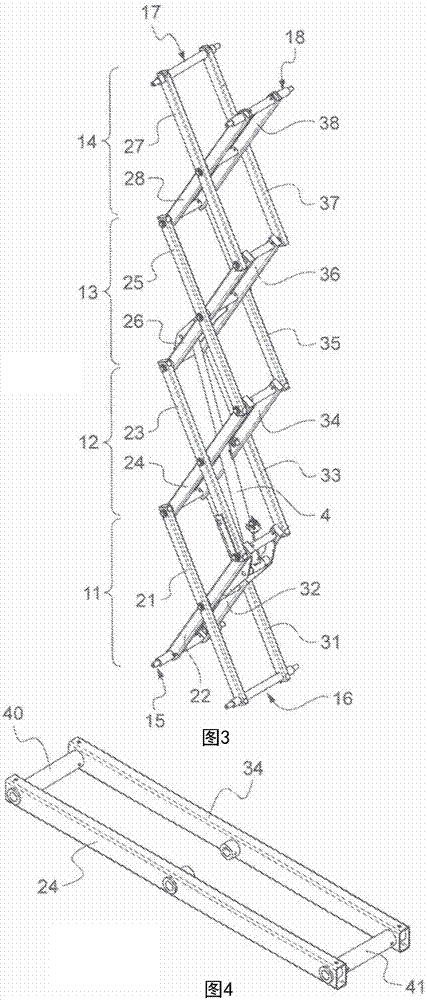
[0066] The overall structure of the lifting mechanism and image 3 similar. As the latter, it consists of two sets of parallel scissors at a distance from each other. Each set of scissors consists of several pairs of tubular beams joined together at their centers like scissors, a plurality of such scissors mounted one above the other by their joined ends: see the stack defining the first set The four pairs (121,122), (123,124), (125,126) and (127,128) of the scissors and the four pairs (131,132), (133,134), (135,136) and (137,138) of the stacked scissors defining the second set. The sections of the tubular beam are preferably rectangular or square...


PUM


Abstract

The invention relates to a scissor arm assembly for a scissor lift, comprising two scissor arms (124, 125) pivotally mounted about a shaft (70). Each arm is made of a tubular beam having a local reinforcement plate (80, 81, 82) welded on either side. Each arm (124, 125) has two through-holes (101, 102; 103, 104) for the shaft (70), each of which is made in a respective side of the beam and the corresponding reinforcement plate. The shaft (70) is circumferentially supported in each hole by both the wall of the beam and the corresponding reinforcement plate (80, 81, 82). The shaft is free of support inside the beam between the two through-holes (101, 102; 103, 104). This avoids having to weld, on either side of the scissor beam, a part inserted therein to house the shaft (70).

Description

technical field [0001] The present invention relates to the field of mobile personnel lifting platforms, further commonly referred to as aerial work platforms. More specifically, the present invention relates to scissor lifts. Background technique [0002] A scissor lift is a machine intended to allow one or several persons to work at heights. They include the chassis, work platform and mechanisms for raising and lowering the work platform. The chassis is mounted on wheels to allow movement of the aerial work platform over the ground. The work platform includes a worktop surrounded by a guardrail. It is arranged to receive a person or persons and optionally load tools such as like paint, cement etc. or other equipment, materials. The working platform is supported by a lifting mechanism installed on the chassis. Lifting mechanisms provide the possibility to raise the working platform from a lower position on the chassis to the desired working height, usually by means of ...

Claims


Application Information

Patent Timeline
Patent Type & Authority Applications(China)
IPC IPC(8): B66F11/04B66F13/00
CPCB66F3/22B66F7/0666B66F9/127B66F11/042
Inventor P·安格拉德
Owner HAULOTTE GROUP
Why Eureka
Try Eureka