
Supply device for automatic assembly machine

A supply device and automatic assembly technology, applied in the direction of electrical components, electrical components, etc., to achieve the effect of high-precision positioning

Active Publication Date: 2016-04-06
ASM ASSEMBLY SYST GMBH & CO
View PDF4 Cites 0 Cited by
  • Summary
  • Abstract
  • Description
  • Claims
  • Application Information

AI Technical Summary

Problems solved by technology

[0008] Of course, all these approaches for starting pulse detection have the disadvantage that, for example, additional mechanical and / or electrical components have to be installed in the supply device
Therefore, associated with it are additional costs and expenses for such components as manufacture, acquisition, installation and maintenance

Method used


Image

  • Supply device for automatic assembly machine
  • Supply device for automatic assembly machine
  • Supply device for automatic assembly machine

Examples


Embodiment Construction

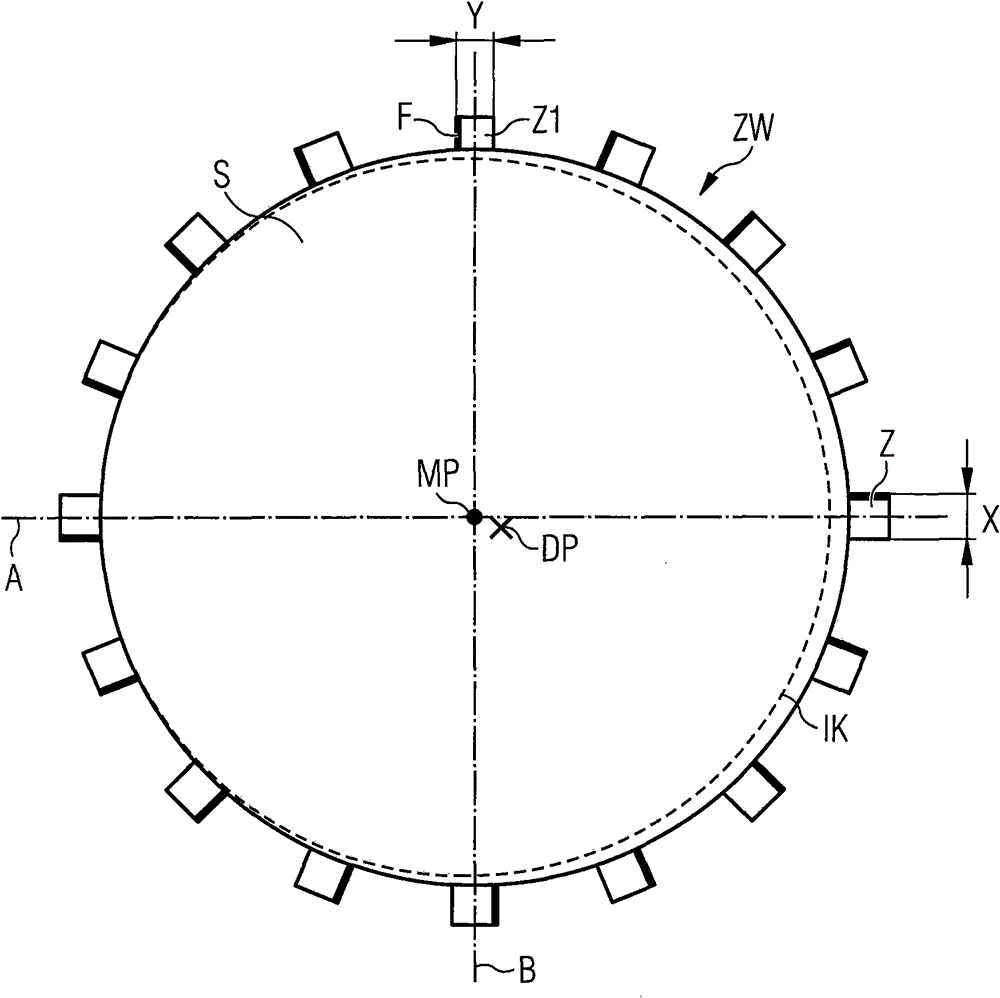
[0028] figure 1 A pin wheel S is shown in a schematic and exemplary manner, which can be used in particular in feeding devices for automatic assembly machines. The pinwheel S has pinwheel teeth Z evenly distributed over the circumference, which are separated by gaps ZW. The pinwheel tooth Z has a width X and a front side F from which the component conveyor belt continues to be conveyed, for example when using the pinwheel S in a feeding device for an automatic assembly machine.

[0029] The pin wheel S is movable around the center of rotation DP. This center of rotation DP may, for example, deviate from the geometric center MP, ie the intersection of lines A and B, due to manufacturing processes. Likewise, for example, the pin wheel S itself may deviate from the ideal circular shape IK due to the manufacturing process. These deviations due to the manufacturing process of the pin wheel S (also referred to as manufacturing tolerances) have a negative effect, especially in the...


PUM


Abstract

The feeder has a needle wheel tooth (Z1) comprising an identifiable width and / or an identifiable height. Gaps are formed between a needle wheel tooth (Z) and the needle wheel tooth (Z1) with an identifiable depth. A driver (AT) i.e. stepper motor, drives a needle wheel (S) to move, and a sensor device (SE) i.e. fork-shaped photoelectric grid, scans the needle wheel teeth. An estimating unit (AW) estimates a signal of the sensor device, where estimating unit clearly identifies the needle wheel tooth (Z1) and the sensor device generates signals. An independent claim is also included for a method for locating elements on a pick-up position in a feeder.

Description

technical field [0001] The invention relates to a feeding device for an automatic assembly machine for transferring components stored on a component conveyor belt to a pick-up position, and to an associated method for carrying out the starting process when using the feeding device according to the invention. start pulse identification. Background technique [0002] During assembly by an automatic assembly machine, supply devices, so-called feeders, are used to supply components for assembling substrates with components. The assembly head of the automatic assembly machine, movable by a positioning system, picks up the components from the supply device in the pick-up position, the assembly head moves to the assembly area of ​​the automatic assembly machine, in which the substrates to be assembled are provided, and the assembly The head places the component on the substrate. Typically components are stored on a component conveyor. For the supply of components, then, a so-cal...

Claims


Application Information

Patent Timeline
Patent Type & Authority Patents(China)
IPC IPC(8): H05K13/02
CPCH05K13/0419
Inventor 马库斯·胡贝尔托马斯·利伯克迪尔克·帕拉斯
Owner ASM ASSEMBLY SYST GMBH & CO
Learn More