

Multidirectional water quality sampling device for drainage and water supply
A sampling device, multi-directional technology, applied to the sampling device and other directions
- Summary
- Abstract
- Description
- Claims
- Application Information
AI Technical Summary
Problems solved by technology
Method used
Image

Examples
Embodiment 1
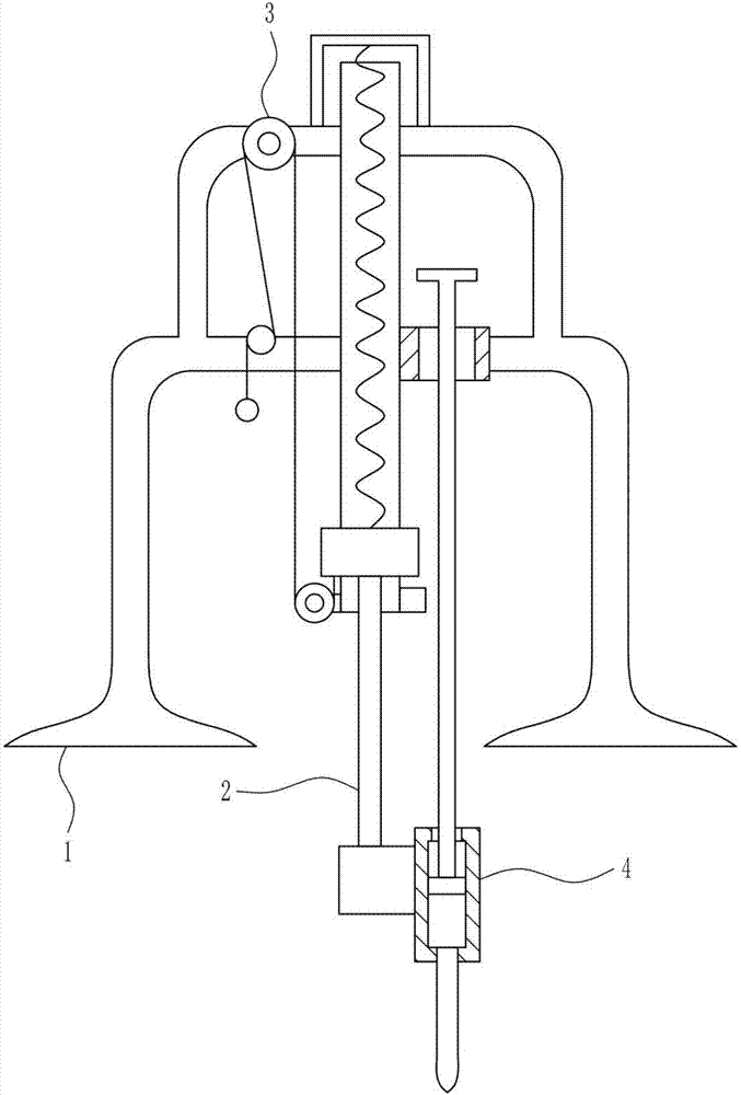
[0036] A multi-directional water quality sampling device for drainage and water supply, such as Figure 1-7 As shown, it includes a mounting frame 1, a lifting rod 2, a lifting mechanism 3, and a sampling mechanism 4. The left side of the front wall of the mounting frame 1 is connected with a lifting mechanism 3, the bottom of the lifting mechanism 3 is connected with a lifting rod 2, and the mounting frame 1 A sampling mechanism 4 is connected to the front wall, and the sampling mechanism 4 is located on the right side of the lifting rod 2.
Embodiment 2
[0038] A multi-directional water quality sampling device for drainage and water supply, such as Figure 1-7 As shown, it includes a mounting frame 1, a lifting rod 2, a lifting mechanism 3, and a sampling mechanism 4. The left side of the front wall of the mounting frame 1 is connected with a lifting mechanism 3, the bottom of the lifting mechanism 3 is connected with a lifting rod 2, and the mounting frame 1 A sampling mechanism 4 is connected to the front wall, and the sampling mechanism 4 is located on the right side of the lifting rod 2.
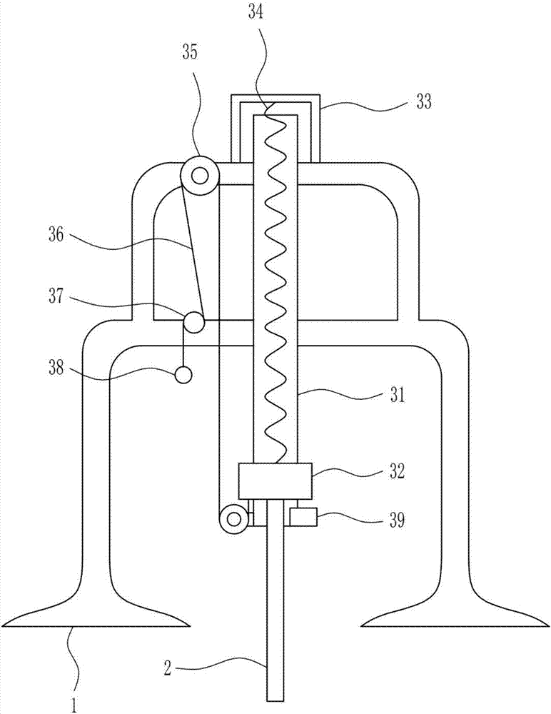
[0039] The lifting mechanism 3 includes a sliding rail 31, a sliding block 32, a first bracket 33, a spring 34, a guide wheel 35, a wire rope 36, a first support rod 37, a pull ring 38 and a stopper 39. The middle of the front wall of the mounting frame 1 is connected There is a sliding rail 31, the sliding rail 31 is slidably connected with a sliding block 32, the sliding rail 31 is matched with the sliding block 32, the top of the mountin...
Embodiment 3
[0041] A multi-directional water quality sampling device for drainage and water supply, such as Figure 1-7 As shown, it includes a mounting frame 1, a lifting rod 2, a lifting mechanism 3, and a sampling mechanism 4. The left side of the front wall of the mounting frame 1 is connected with a lifting mechanism 3, the bottom of the lifting mechanism 3 is connected with a lifting rod 2, and the mounting frame 1 A sampling mechanism 4 is connected to the front wall, and the sampling mechanism 4 is located on the right side of the lifting rod 2.
[0042] The lifting mechanism 3 includes a sliding rail 31, a sliding block 32, a first bracket 33, a spring 34, a guide wheel 35, a wire rope 36, a first support rod 37, a pull ring 38 and a stopper 39. The middle of the front wall of the mounting frame 1 is connected There is a sliding rail 31, the sliding rail 31 is slidably connected with a sliding block 32, the sliding rail 31 is matched with the sliding block 32, the top of the mountin...
PUM
 Abstract
Description
Claims
Application Information