a protective relay

A relay and protective resistor technology, applied in the field of protective relays, can solve the problems of easily damaged relays, current-damaged relays, and weak installation of protective resistors, and achieve the effect of stable structure and good protection.

Active Publication Date: 2020-08-18
SANYOU CORP LTD
View PDF7 Cites 0 Cited by
  • Summary
  • Abstract
  • Description
  • Claims
  • Application Information

AI Technical Summary

Problems solved by technology

[0003] At present, the relays on the market have an interactive relationship between the control system (also known as the input circuit) and the controlled system (also known as the output circuit), but there is a problem that the control system is in a power-on state for a long time and it is easy to damage the relay. A protective resistor, but the protective resistor is not installed firmly in the relay, and it is easy to make poor contact, resulting in excessive current damage to the relay

Method used


Image

  • a protective relay
  • a protective relay
  • a protective relay

Examples


Embodiment Construction

[0030] The present invention will be further described in conjunction with the following embodiments and accompanying drawings.

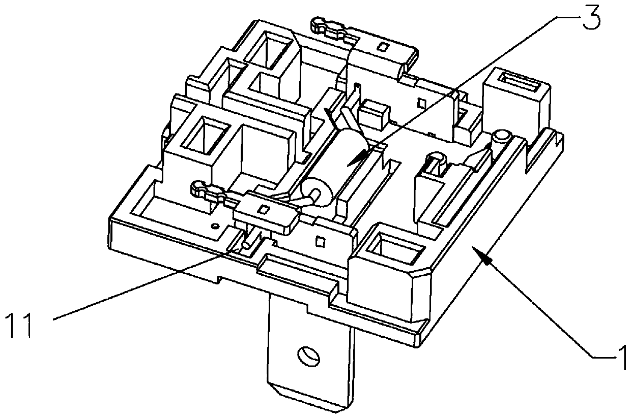
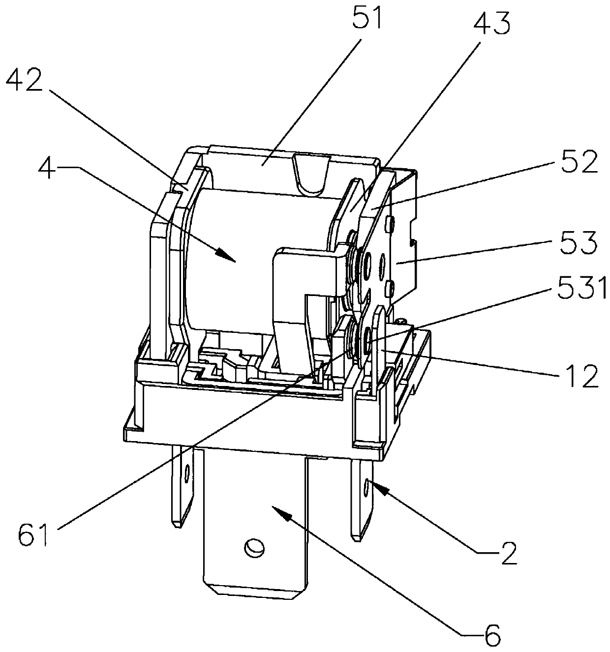
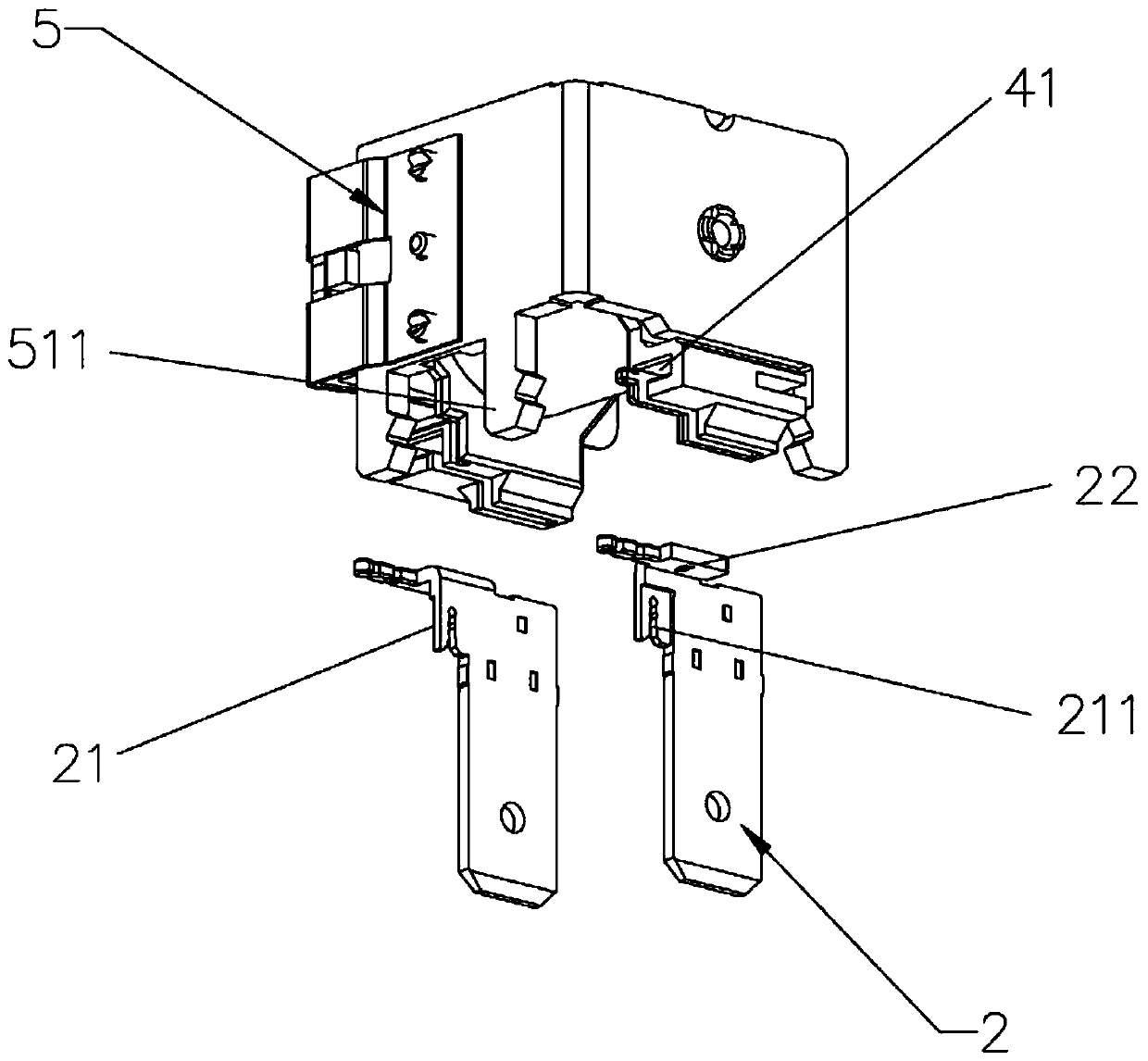
[0031] Such as Figure 1 to Figure 4 As shown, a protective relay includes a bottom case 1, two power terminals 2 inserted in the bottom case 1 and a protective resistor 3 connected between the two power terminals 2, and the bottom case 1 is provided for accommodating The installation groove 11 of the protective resistor 3 is provided, and each power terminal 2 is provided with a clamping part 21, and the clamping part 21 is provided with a clamping groove 211, and the two ends of the protective resistor 3 are respectively installed in two clamping grooves In 211 , the clamping portion 21 is accommodated in the installation groove 11 . A protective relay, the power terminal 2 is provided with a clamping part 21 for clamping the protective resistor 3, the clamping part 21 is provided with a clamping groove 211 for clamping the protective resistor 3,...


PUM


Abstract

The invention relates to the technical field of relays, in particular to a protective relay which comprises a bottom shell, two power terminals inserted in the bottom shell and a protection resistor connected between the two power terminals. The bottom shell is provided with a mounting groove for containing the protection resistor. Each power terminal is provided with a clamping part, the clampingpart is provided with a clamping groove, the two ends of the protection resistor are installed in the two clamping grooves respectively, and the clamping part is accommodated in the mounting groove.In the protective relay, each power terminal is provided with the clamping part for clamping the protection resistor, and the clamping part is provided with the clamping groove for clamping the protection resistor. The bottom shell is provided with the mounting groove for accommodating the clamping part, so that the protection resistor is clamped in the clamping groove and installed in the mounting groove, and the protection resistor is installed firmly and is stable in structure and good in protective property.

Description

technical field [0001] The invention relates to the technical field of relays, in particular to a protection relay. Background technique [0002] The relay is an electric control device, which is an electrical appliance that causes the controlled quantity to undergo a predetermined step change in the electrical output circuit when the change of the input quantity (excitation quantity) meets the specified requirements. It has an interactive relationship between the control system (also known as the input loop) and the controlled system (also known as the output loop). Usually used in automatic control circuits, it is actually an "automatic switch" that uses a small current to control the operation of a large current. Therefore, it plays the role of automatic adjustment, safety protection, and conversion circuit in the circuit. [0003] At present, the relays on the market have an interactive relationship between the control system (also known as the input circuit) and the c...

Claims


Application Information

Patent Timeline
Patent Type & Authority Patents(China)
IPC IPC(8): H01H50/02H01H50/04H01H50/14
Inventor 刘振伟
Owner SANYOU CORP LTD
Why Eureka
Try Eureka