
Novel smokeless electric oven

An electric oven, a new type of technology, applied in the direction of roaster/barbecue grid, kitchen utensils, household utensils, etc., can solve the problems of high production cost and use cost, large cost investment, environmental impact, etc., to achieve low manufacturing cost, Low cost and reduced oil loss

Active Publication Date: 2018-01-09
唐海云
View PDF6 Cites 0 Cited by
  • Summary
  • Abstract
  • Description
  • Claims
  • Application Information

AI Technical Summary

Problems solved by technology

However, when realizing the above-mentioned "smoke-free" effect, it is necessary to add many devices, such as purifiers, filters, etc., and the cost of these devices is large, so that the cost of the smoke-free oven in the prior art is high. The cost is high, because the work of the purifier and the filter needs to consume a large amount of electric energy, so the smokeless oven in the prior art, its production cost and use cost are all very large
In addition, due to the limitations of the development of filtration and purification technology, the smokeless ovens in the prior art still produce oil fume, which still has an impact on the environment

Method used


Image

  • Novel smokeless electric oven
  • Novel smokeless electric oven
  • Novel smokeless electric oven

Examples


Embodiment 1

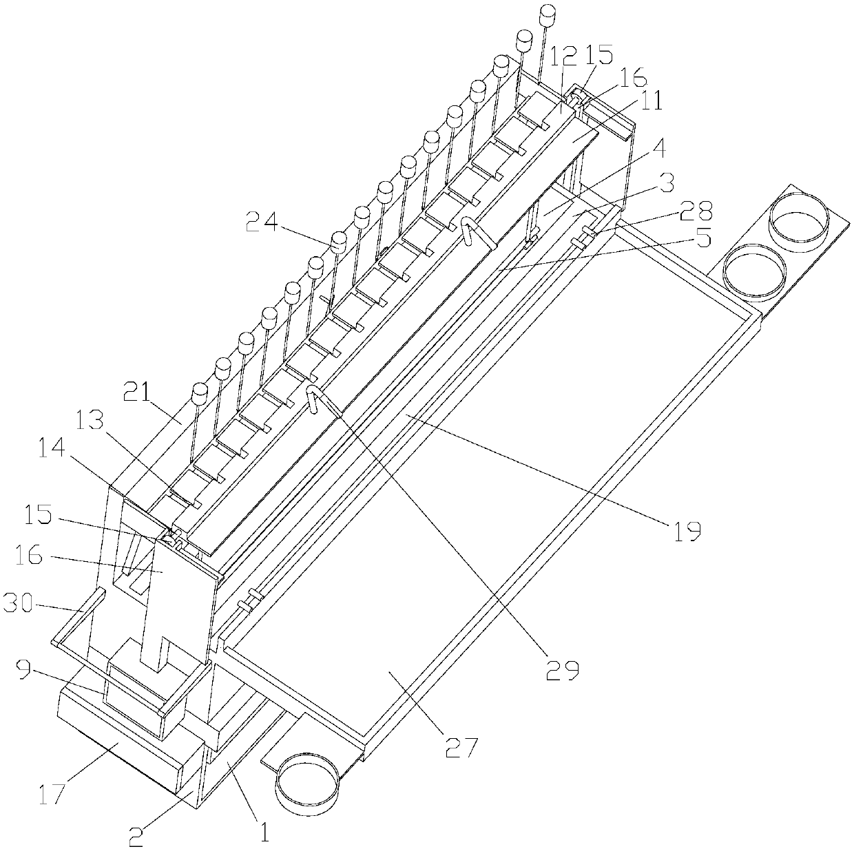
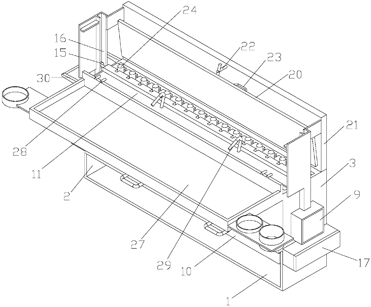
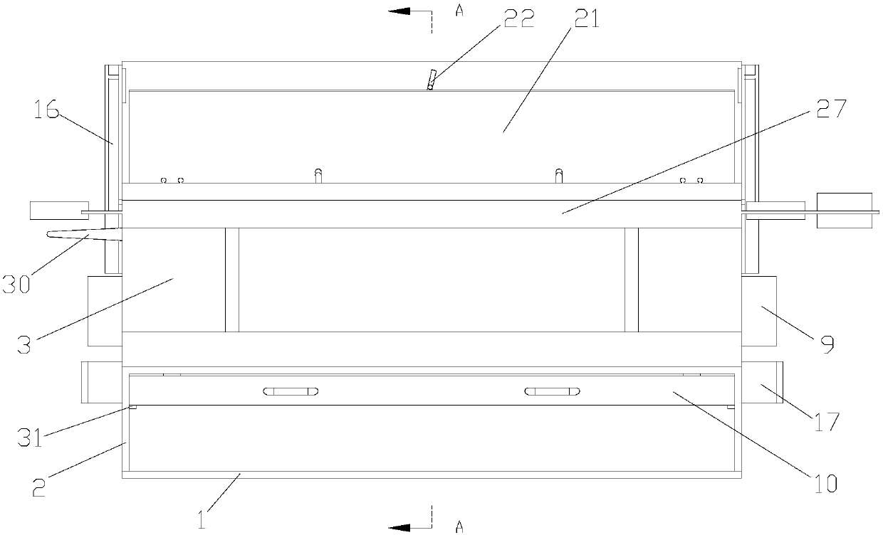
[0039] In this embodiment, a new smokeless electric oven includes a bottom plate 1. As the best implementation mode of this embodiment, the above-mentioned bottom plate 1 is a rectangular plate. The left and right ends of the upper surface of the above-mentioned bottom plate 1 are respectively provided with supports Plate 2, a furnace body 3 is lapped between the support plates 2 at the left and right ends of the bottom plate 1, and the function of the support plate 2 is to vacate the furnace body 3. As another implementation of this embodiment, a bracket may be provided on the lower surface of the furnace body 3 , as long as the furnace body can be vacated.

[0040] In this embodiment, the furnace body is in the shape of a cuboid, and its left end is lapped on the upper surface of the support plate 2 installed on the left end of the bottom plate 1, and its right end is lapped on the upper surface of the support plate 2 installed on the right end of the bottom plate 1. The fur...

Embodiment 2

[0046] This embodiment is further improved on the basis of Embodiment 1. As shown, in this embodiment, the number of the above-mentioned heating tubes 5 is limited to more than one. Several protrusions 8 are arranged side by side on the inner side wall of the above-mentioned barbecue chamber 4. As the best implementation mode of this embodiment, the above-mentioned protrusions 8 are arranged on the front and rear side walls of the above-mentioned barbecue chamber 4, and the above-mentioned protrusions 8 is a strip structure with a triangular cross section. In this embodiment, in order to make the heat generated by the heating tube 5 more concentrated in the above-mentioned barbecue chamber 4, a heating tube 5 is arranged between every two adjacent protrusions 8, so that the heating tube 5 radiates The heat emitted will be reflected and concentrated on the slope of the above-mentioned protrusion 8. The above-mentioned design can not only improve the heating efficiency during th...

Embodiment 3

[0048] This embodiment is further defined and improved on the basis of the above-mentioned embodiments. In this embodiment, the above-mentioned heating tube 5 is limited to be an electric heating tube in order to improve its controllability. Of course, the above-mentioned heating tube 5 can also be any other heating tube. source. The electrode terminals of the heating pipe 5 are located at the left and right ends of the above-mentioned heating pipe 5. When it is specifically installed, the above-mentioned electrode terminals are placed outside the above-mentioned barbecue chamber 4, and the left end electrode terminals of the plurality of heating pipes 5 and the plurality of hairs The right end electrode terminals of the heat pipes 5 are respectively connected in series. With the above-mentioned structure, in the case of electrification, several above-mentioned heat pipes 5 will generate heat at the same time, so that when grilling, the heat pipes 5 can heat the food. It is mo...


PUM


Abstract

The invention belongs to the field of cookers and relates to a novel smokeless electric oven. The novel smokeless electric oven comprises a bottom plate, supporting plates, an oven body, heating tubesand a V-shaped channel. The supporting plates are arranged at left and right ends of the upper surface of the bottom plate, and the oven body is supported between the supporting plates mounted at theleft and right ends of the bottom plate. The oven body is provided with a barbecue cavity penetrating the oven body vertically, and the heating tubes are mounted between left and right side walls ofthe barbecue cavity and tightly attached to front and rear side walls of the barbecue cavity. The V-shaped channel with an upward opening is mounted at the bottom of the barbecue cavity, the heating tubes are positioned above the V-shaped channel, and the bottom wall of the V-shaped channel is provided with an oil groove in communication with the barbecue cavity. By adoption of the structure, oildrops generated by foods are prevented from dripping to the inner wall of the hot barbecue cavity in barbecuing, so that oil drop vaporization is avoided, and a whole process is free of smoke. In addition, the novel smokeless electric oven has advantages of simple structure, low manufacturing and utilization cost and high usability.

Description

technical field [0001] The invention belongs to the field of cooking utensils, in particular to a novel smokeless electric oven. Background technique [0002] Barbecue is the most primitive cooking method for human beings. It uses fuel to heat and dry the air, and places the food in the hot dry air at a position closer to the heat source to heat the food. Generally speaking, barbecue is to cook food (mostly meat, seafood, vegetables) on fire until it is edible, so some places also call it barbecue; in modern society, because there are many ways to use fire, barbecue methods are also different. Gradually diversify, and develop all kinds of barbecue ovens, barbecue racks, barbecue sauces, etc. Out of environmental protection considerations, some smokeless ovens have appeared in real life, which achieve a "smoke-free" effect by purifying and filtering the oil fumes generated during the barbecue process. However, when realizing the above-mentioned "smoke-free" effect, it is ne...

Claims


Application Information

Patent Timeline
Patent Type & Authority Applications(China)
IPC IPC(8): A47J37/06
Inventor 唐海云
Owner 唐海云
Learn More