

Carbon powder mixing device
A technology of mixing device and carbon powder, applied in mixer, mixer with rotary stirring device, dissolving and other directions, can solve the problem that carbon powder and auxiliary agent are difficult to fall out, toner powder and auxiliary agent are mixed evenly, and carbon powder pollutes the air. And other issues
- Summary
- Abstract
- Description
- Claims
- Application Information
AI Technical Summary
Problems solved by technology
Method used
Image

Examples
Embodiment 1
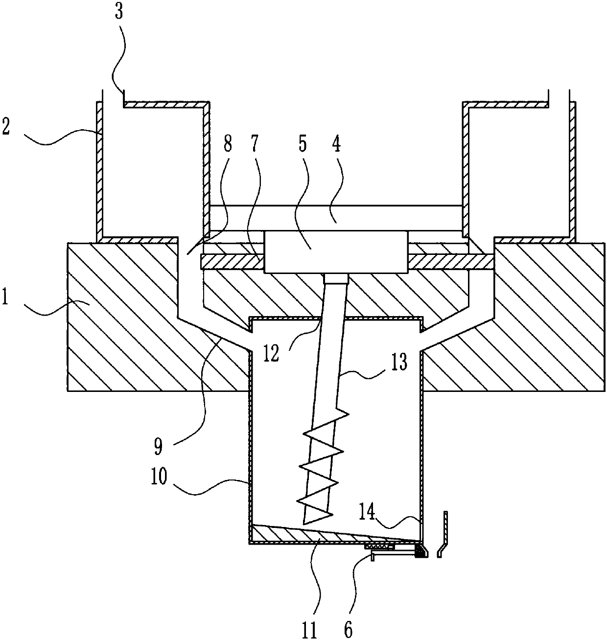
[0034] A toner mixing device such as Figure 1-7 As shown, it includes a mounting plate 1, a feeding box 2, a feeding pipe 3, a first baffle 7, a driving mechanism 5, a discharging mechanism 6, a first connecting plate 4, a guide plate 8, a discharging pipe 9, and a stirring box 10. Inclined plate 11 and stirring rod 13. Feeding box 2 is provided on the left and right sides of the top of mounting plate 1. The bottom of feeding box 2 is connected with discharge pipe 9. The right wall of left feeding box 2 and the left side of right feeding box 2 The lower side of the wall is provided with a guide plate 8, the guide plate 8 is located in the discharge pipe 9, the front side of the installation plate 1 is provided with a stirring box 10, the middle of the top of the stirring box 10 has a first through hole 12, and the left and right walls of the stirring box 10 The side is connected to the end of the discharge pipe 9, the first connecting plate 4 is connected between the left and...
Embodiment 2
[0036] A toner mixing device such as Figure 1-7 As shown, it includes a mounting plate 1, a feeding box 2, a feeding pipe 3, a first baffle 7, a driving mechanism 5, a discharging mechanism 6, a first connecting plate 4, a guide plate 8, a discharging pipe 9, and a stirring box 10. Inclined plate 11 and stirring rod 13. Feeding box 2 is provided on the left and right sides of the top of mounting plate 1. The bottom of feeding box 2 is connected with discharge pipe 9. The right wall of left feeding box 2 and the left side of right feeding box 2 The lower side of the wall is provided with a guide plate 8, the guide plate 8 is located in the discharge pipe 9, the front side of the installation plate 1 is provided with a stirring box 10, the middle of the top of the stirring box 10 has a first through hole 12, and the left and right walls of the stirring box 10 The side is connected to the end of the discharge pipe 9, the first connecting plate 4 is connected between the left and...
Embodiment 3
[0039] A toner mixing device such as Figure 1-7 As shown, it includes a mounting plate 1, a feeding box 2, a feeding pipe 3, a first baffle 7, a driving mechanism 5, a discharging mechanism 6, a first connecting plate 4, a guide plate 8, a discharging pipe 9, and a stirring box 10. Inclined plate 11 and stirring rod 13. Feeding box 2 is provided on the left and right sides of the top of mounting plate 1. The bottom of feeding box 2 is connected with discharge pipe 9. The right wall of left feeding box 2 and the left side of right feeding box 2 The lower side of the wall is provided with a guide plate 8, the guide plate 8 is located in the discharge pipe 9, the front side of the installation plate 1 is provided with a stirring box 10, the middle of the top of the stirring box 10 has a first through hole 12, and the left and right walls of the stirring box 10 The side is connected to the end of the discharge pipe 9, the first connecting plate 4 is connected between the left and...
PUM
 Abstract
Description
Claims
Application Information