A rotating lifting device

A lifting device and rotating block technology, which is applied in spraying devices, spraying devices with movable outlets, etc., can solve the problems of inability to control the speed, affect the treatment effect, and operator fatigue, and achieve accurate swing angle and speed, and good water vapor isolation The effect of action

Active Publication Date: 2021-11-05
SHANGHAI UNIV
View PDF7 Cites 0 Cited by
  • Summary
  • Abstract
  • Description
  • Claims
  • Application Information

AI Technical Summary

Problems solved by technology

The speed cannot be controlled during the operation, and the long-term swing operation is likely to cause fatigue of the operator and affect the processing effect

Method used


Image

  • A rotating lifting device
  • A rotating lifting device
  • A rotating lifting device

Examples


Embodiment 1

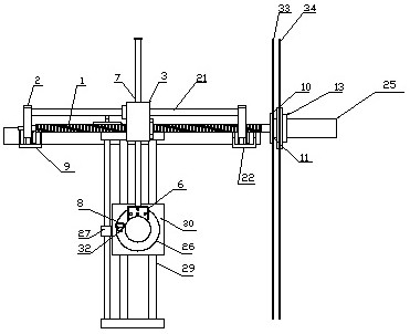
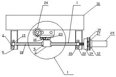
[0024] The rotary lifting device includes a fixed bracket (I), a servo motor (25), a hand wheel (24), a moving mechanism (II), a lifting mechanism (III) and a working disk (26) for installing tools, It is characterized in that: the servo motor (25), the handwheel (24), the moving mechanism (II) and the lifting mechanism (III) are installed on a fixed bracket (I); the servo motor (25) is connected to the moving mechanism (II ) and drive a moving block (3) on the mechanism to move left and right. The moving block (3) is connected to a lifting moving block (6) on the lifting mechanism through a swing rod (7), and drives it to rotate; the handwheel (24) is connected to the lifting mechanism and drives one of the lifting blocks (30 ) for lifting movement; the working turntable (26) is fixedly connected with the lifting rotating block (6), and the working turntable (26) is connected with the lifting block (30) in rotation with the same axis. Operating the servo motor (25) and / or th...

Embodiment 2

[0026] The fixed bracket (I) includes square steel (31), L-shaped plate armor (21) and L-shaped plate B (22), the square steel (31) is welded on the original working equipment, and the L-shaped plate armor (9 ) and L-type plate second (22) by being fixed on the square steel (31).

[0027] The moving mechanism (II) includes a ball screw (1), a screw mount (2), a moving block (3), a rotating block (4), a linear bearing (5), an adapter block (6), a pendulum Rod (7), flange (10), waterproof gasket (11), adapter sleeve (12), motor seat (13), clamping plate (14), bearings (15, 16, 17), mold guide sleeve (18), bending piece (19), screw mounting seat B (20), guide rod A (21), cover (23), inner plate (33) and outer plate (34), the screw rod installation Seat A (2) and screw mounting seat B (20) are respectively fixed on L-shaped plate A (9) and L-shaped plate B (22), supporting guide rod A (21) and ball screw

[0028] (1), the ball screw (1) cooperates with the screw mount A (2) and ...

Embodiment 3

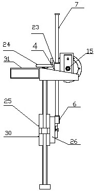
[0030] The lifting mechanism (Ⅲ) includes a U piece (8), a hand wheel (24), a screw nut (27), an ordinary screw rod (28), a guide rod B (29) and a lifting block (30). The block (30) is connected with the working turntable (26), after inserting the U (8) piece to jack up the spring pin (32), the working turntable (26) can rotate around the axis relative to the lifting block (30), when the fork ( 7) When swinging, the working disc (26) rotates together with the swing rod (7) in the moving mechanism (II) to complete the rotation. The lifting block (30) slides on the guide rod B (29), and can move up and down along the guide rod B (29). After the bolt on the back of the lifting block (30) is locked, its position is fixed; the screw nut (27 ) is matched with the ordinary screw rod (28) and fixed on the side of the lifting block (30). ) to move up and down to complete the lifting action.


PUM


Abstract

The invention relates to a rotary lifting device. Consists of fixed brackets, a servo motor, a hand wheel, a moving mechanism, a lifting mechanism and a work plate for mounting tools. The servo motor, hand wheel, moving mechanism and lifting mechanism are installed on the fixed bracket; the servo motor is connected to the moving mechanism and drives a moving block on the mechanism to move left and right, and the moving block is connected to the lifting mechanism through a swing rod One of the lifting moving blocks, and drives it to rotate; the hand wheel is connected to the lifting mechanism and drives one of the lifting blocks to move up and down; the working turntable is fixedly connected to the lifting rotating block, and the working turntable and the lifting block rotate coaxially Connection; operating the servo motor and / or the hand wheel can realize the rotation and / or lifting movement of the working turntable. It can be used to install sprinklers to rotate according to a specific sinusoidal curve.

Description

technical field [0001] The invention relates to a rotating lifting device, which can be used in a high-pressure water spraying device and can ensure that the water spraying rotating device rotates according to a specific sinusoidal curve. [0002] technical background [0003] Automotive exterior decoration is the key to whether a car is beautiful, and a beautiful car must have high-quality exterior materials. During the development process, designers need to conduct various inspections on the exterior, among which the use of high-pressure water spray devices to remove the treatment layer on the surface of the material is a key step. The traditional water spray device can use the screw rod lifting mechanism to turn the hand wheel to adjust the height of the nozzle, but it lacks a rotating device, which makes it difficult to process large-area materials. [0004] Although some equipment has added adjustment devices, manual adjustment is still adopted, relying on the subjectiv...

Claims


Application Information

Patent Timeline
Patent Type & Authority Patents(China)
IPC IPC(8): B05B3/14B05B15/68
Inventor 周舟王志明畅妍妍方征刘岩
Owner SHANGHAI UNIV
Why Eureka
Try Eureka