Punching die system long in life

A technology of life and die, applied in the field of stamping die, can solve the problems of roller maintenance, replacement, time-consuming and laborious, complicated maintenance operations, etc., and achieves the effect of good anti-detachment effect, convenient unlocking operation, and simple operation.

Inactive Publication Date: 2018-01-09
余永海
View PDF6 Cites 10 Cited by
  • Summary
  • Abstract
  • Description
  • Claims
  • Application Information

AI Technical Summary

Problems solved by technology

Among them, the most commonly used conveying equipment is the roller conveyor. However, the existing roller conveyors have the problem of difficult maintenance and replacement of the rollers.
Therefore, when performing maintenance, it is necessary to disassemble the entire panel on one side of the roller conveyor, and then separate the roller from the chain before removing the roller. The maintenance operation is complicated, time-consuming and laborious

Method used


Image

  • Punching die system long in life
  • Punching die system long in life
  • Punching die system long in life

Examples


Embodiment Construction

[0020] In order to enable those skilled in the art to better understand the solutions of the present invention, the technical solutions in the embodiments of the present invention will be clearly and completely described below in conjunction with the drawings in the embodiments of the present invention.

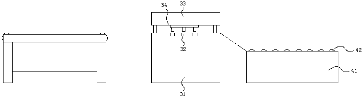
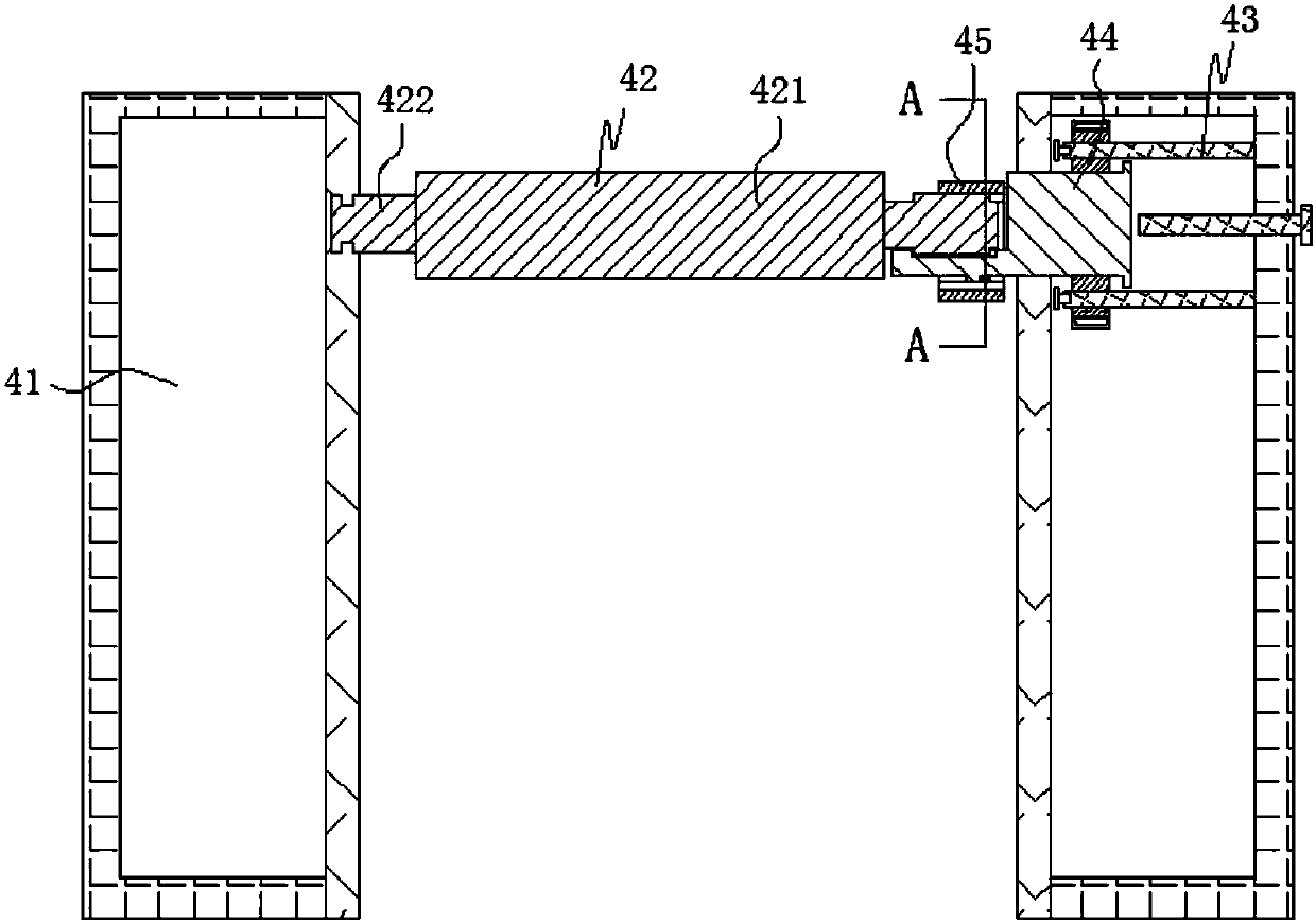
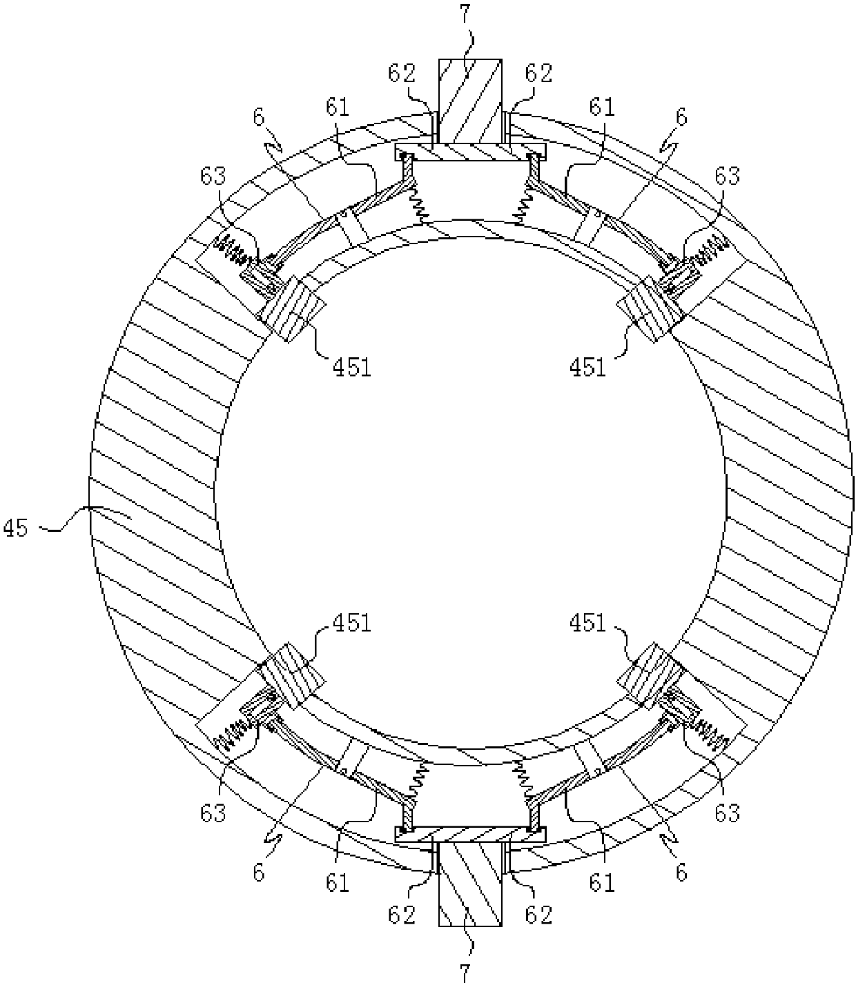
[0021] Such as Figure 1-6 As shown, a high-life punching die system includes a feeding unit, a stamping unit, and a discharge unit; the stamping unit includes a lower die 31, a stamping cavity 32 arranged on the lower die, and an upper die that can move up and down relative to the lower die 33 and the pressure column 34 located on the upper die; the shape of the stamping cavity 32 depends on the actual shape of the workpiece to be stamped, so it is not limited; the upper die 33 is connected with 4 drive columns, and the drive The columns are respectively connected with a cylinder, and the upper mold can be driven to move up and down by driving the column up and down through ...


PUM


Abstract

The invention discloses a punching die system which is long in life. The punching die system comprises a conveying mechanism, a box body forming mechanism, a top folding mechanism and a glue sealing mechanism; the conveying mechanism comprises conveying brackets, a plurality of conveying drums distributed in a spaced manner in the length directions of the conveying brackets, driving components fordriving the conveying drums to rotate, and cover pieces matched with the driving components in a telescopic movement manner; each conveying drum comprises a body part, a connecting part, and a connecting part matched with the corresponding cover piece; disengagement prevention pieces matched with the corresponding cover piece in a disengagement prevention manner, and an unlocking device are arranged on each connecting part matched with the corresponding cover piece; and each unlocking device is used for removing the disengagement prevention matching between one cover piece and the corresponding disengagement prevention pieces. With the arrangement of the cover pieces, the lengths of the conveying drums can be set to be less than the distance between the left conveying bracket and the right conveying bracket, so that when the disengagement prevention matching between each cover piece is the corresponding connecting part is removed, the cover pieces can retract into the corresponding conveying bracket, the conveying drums can be taken down and taken out directly from the conveying brackets, the disassembly and assembly are convenient, and the punching die system is convenient for maintenance.

Description

technical field [0001] The invention belongs to the technical field of punching dies, in particular to a high-life punching die system. Background technique [0002] Stamping is a pressure processing method that uses a mold installed on a press to apply pressure to a material at room temperature to cause separation or plastic deformation to obtain the required parts. The most common method of existing stamping is to cold stamp the workpiece through the stamping die, and the stamped workpiece is then transported to the next link through the conveying equipment, and the workers inspect, pack and leave the warehouse. Among them, the most commonly used conveying equipment is the roller conveyor. However, the existing roller conveyors all have the problem of difficult maintenance and replacement of the rollers. Therefore, when performing maintenance, it is necessary to disassemble the entire panel on one side of the roller conveyor, and then separate the roller from the chain be...

Claims


Application Information

Patent Timeline
Patent Type & Authority Applications(China)
IPC IPC(8): B21D37/12B21D45/02
Inventor 余永海
Owner 余永海
Why Eureka
Try Eureka