Total reflection focusing method and device used for LED shadowproof lamp

A technology of LED shadowless lamp and focusing device, applied in the direction of reflector, lighting device, lighting device components, etc., can solve the problems of glare, low heat, short optical path, etc., and achieve the effect of fast heat dissipation, low heat generation, and short optical path

Pending Publication Date: 2018-01-09
HUNAN TAIYANGLONG MEDICAL TECH
View PDF15 Cites 1 Cited by
  • Summary
  • Abstract
  • Description
  • Claims
  • Application Information

AI Technical Summary

Problems solved by technology

[0003] The purpose of the present invention is to solve the problems of light loss and glare in the existing shadowless operating lamp, and seek a focusing method with short optical path and high effective utilization of light, and redesign and provide a kind of total reflection focusing for LED shadowless lamp The method and the device, the method and the device focus the light source to the shadowless illumination area by using the total reflection method, the device configured by this method and its LED shadowless lamp can achieve better illuminance with less power, and the heat generated by it Small, and the total reflection method will not have the problem of light loss, and can form a more uniform and delicate shadowless spot, so that the visual effect of the shadowless illumination area is better

Method used


Image

  • Total reflection focusing method and device used for LED shadowproof lamp
  • Total reflection focusing method and device used for LED shadowproof lamp
  • Total reflection focusing method and device used for LED shadowproof lamp

Examples


Embodiment Construction

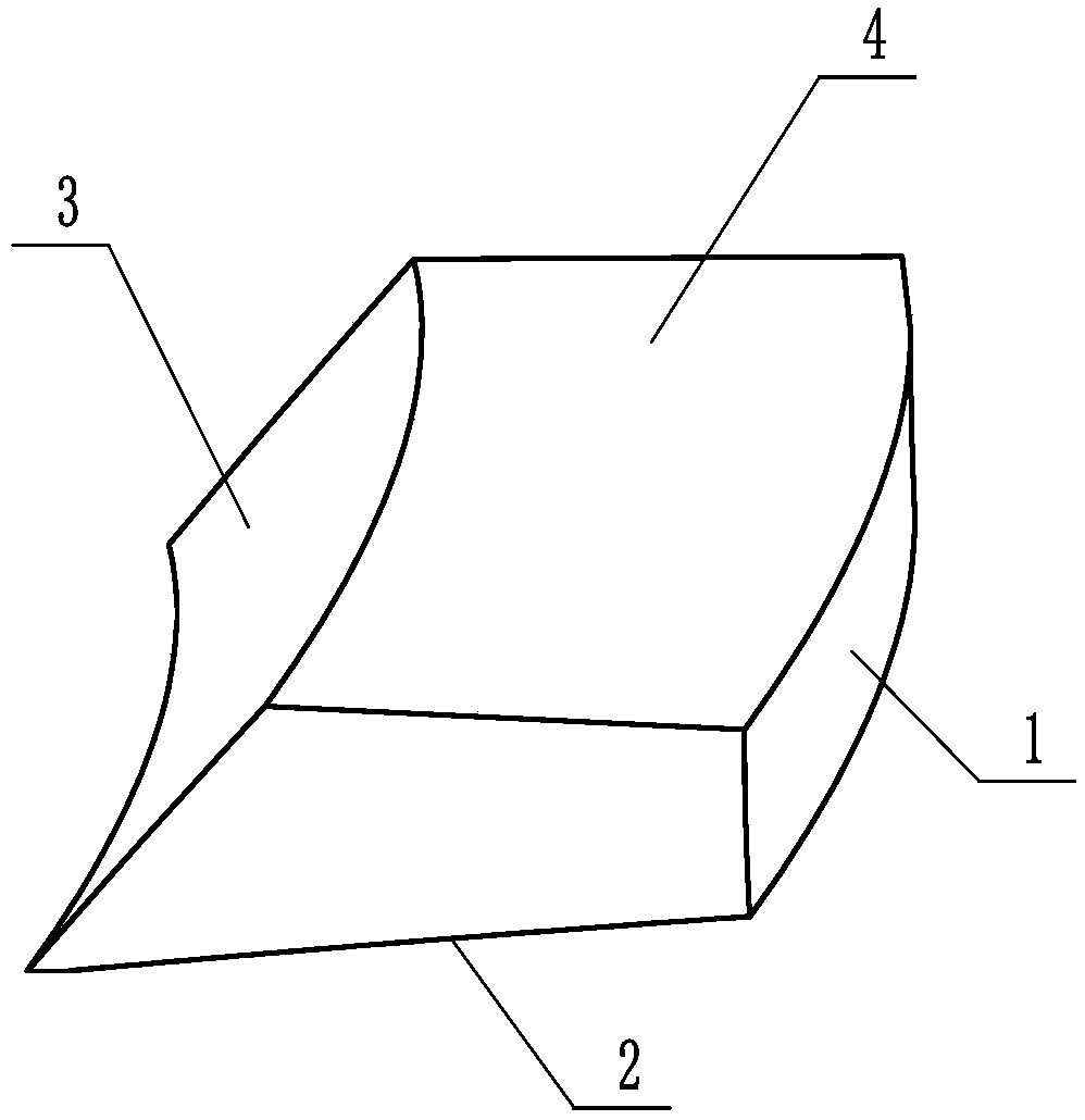
[0030] The present invention will now be described in further detail with reference to preferred embodiments shown in the accompanying drawings.

[0031] For a thorough understanding of the present invention, numerous specific details are shown in the following description of the preferred embodiments, however it will be apparent to those skilled in the art that the present invention may be practiced without some or all of these specific details, but No matter how it is implemented, the content of the present invention is not limited by its shape and structure, as long as the technical method of the present invention is adopted, it should be included in the embodiment of the present invention.

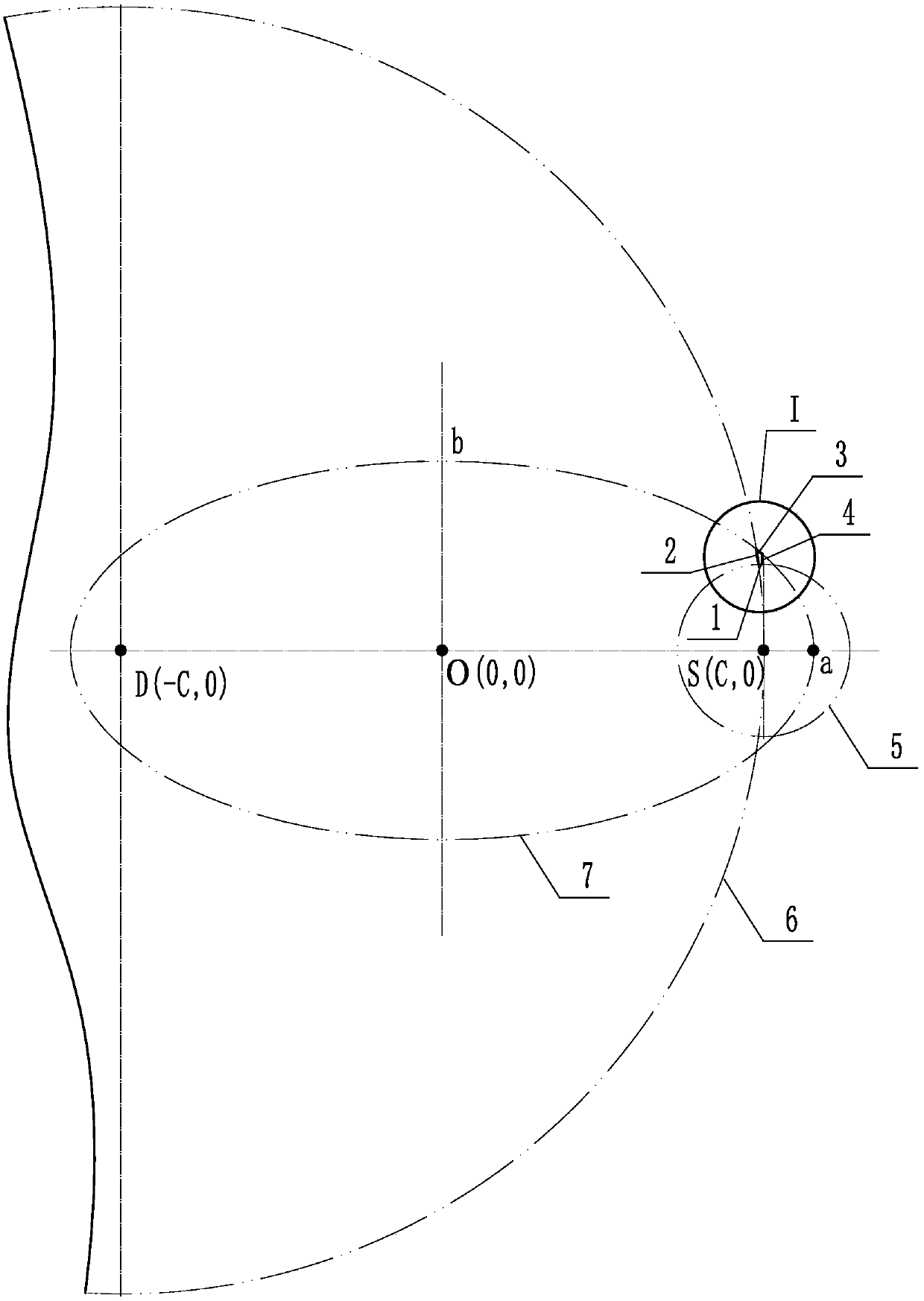
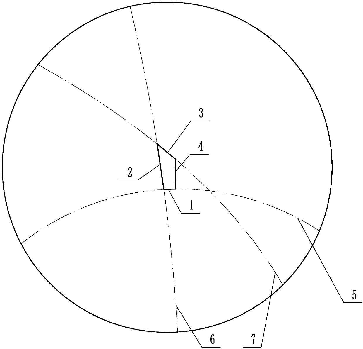
[0032] In order to achieve the purpose of the present invention, according to the principle of total reflection, total reflection will occur when the value of the square of the sine minus the square of the cosine is negative, and the critical value is zero. For reflection, the total re...


PUM


Abstract

The invention discloses a total reflection focusing method and device used for an LED shadowproof lamp. The method and device are characterized in that the device comprises a total reflection focusingdevice unit; with a point S and a point D as the circle centers, a circle S and a circle D intersecting with the circle S are formed correspondingly; with the circle centers of the circle S and the circle D as the focal points, a conjugated ellipse is formed; total reflection surfaces of the total reflection focusing device unit are located on a curve section of the ellipse, and when incident light emitted from the point S irradiates the total reflection surfaces located on the curve section of the ellipse in the mode that the incidence angle alpha is greater than or equal to the critical angle of a total reflection focusing device, the incident light can be totally reflected to the point D; and incident planes are formed between the points of intersection of the circle S and the circle Dand the points of intersection of the circle S and the ellipse, light-exiting surfaces are formed between the points of intersection of the circle S and the circle D and the points of intersection ofthe circle D and the ellipse, and the total reflection surfaces are formed on the curved section between the points of intersection of the ellipse and the circle S and the points of intersection of the ellipse and the circle D. The total reflection focusing method and device provided by the invention have the advantages that the light path is short, the light loss is small, the light utilizationrate is higher, a required lamp is low in power and small in heating capacity, formed light spots are fine and smooth, and glare is avoided.

Description

technical field [0001] The invention relates to a total reflection focusing method and device for an LED shadowless lamp, and belongs to the field of medical shadowless surgical lamps. Background technique [0002] In the prior art, LED shadowless lamps used in hospital operating rooms generally use reflection to focus the light source to form a shadowless illumination area, but there are generally defects such as excessive light loss or high requirements for reflective media. In order to achieve a shadowless illumination area for surgery The required spot illuminance needs to be realized by lamps with higher power, so the heat generated is large, the heat dissipation of lamps is slow, the attenuation of light is aggravated, and the lighting effect and service life of shadowless lamps are affected. The formed spot is large and cannot be formed. The smaller shadowless light area will also produce glare and other defects that are not conducive to surgery, which is no longer su...

Claims


Application Information

Patent Timeline
Patent Type & Authority Applications(China)
IPC IPC(8): F21V7/04F21V7/22F21Y115/10
Inventor 不公告发明人
Owner HUNAN TAIYANGLONG MEDICAL TECH
Why Eureka
Try Eureka