Eureka AIR delivers breakthrough ideas for toughest innovation challenges, trusted by R&D personnel around the world.

Special fiber drying machine

A special fiber and drying machine technology, which is applied in the direction of local stirring dryers, static material dryers, dryers, etc., can solve the problems of poor drying effect and achieve the effect of improving drying efficiency and effect

Active Publication Date: 2018-01-09
常州市盛杰合力化纤有限公司
View PDF8 Cites 2 Cited by
  • Summary
  • Abstract
  • Description
  • Claims
  • Application Information

AI Technical Summary

Problems solved by technology

[0002] As we all know, special fibers are fiber structures manufactured by related fiber manufacturing enterprises, which have special physical and chemical structures, properties and uses, or chemical fibers with special functions, and are mostly used in the fields of industry, national defense, medical care, environmental protection and cutting-edge science. The special fiber dryer is an auxiliary device for drying special fibers after washing, and is especially widely used in the above-mentioned manufacturing enterprises; the existing special fiber dryer includes a main body, a placement frame and an electric heater. There is a placement cavity, the front side of the main body is provided with a pick-and-place opening, and a door is set at the pick-and-place opening, the placement rack and the electric heater are located in the placement cavity; when this special fiber dryer is used, it uses the special The fibers can be placed on the rack and dried by electric heating through electric heaters; it is found that the drying effect is poor

Method used


Image

  • Special fiber drying machine

Examples


Embodiment Construction

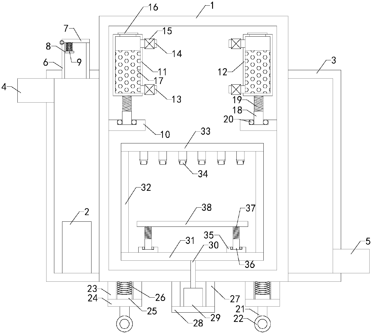
[0013] The specific implementation manners of the present invention will be further described in detail below in conjunction with the accompanying drawings and embodiments. The following examples are used to illustrate the present invention, but are not intended to limit the scope of the present invention.

[0014] Such as figure 1 As shown, the special fiber dryer of the present invention includes a main body 1, a placement rack and an electric heater 2, a placement cavity is provided inside the main body, a pick-and-place opening is provided on the front side of the main body, and a pick-and-place opening is provided at the pick-and-place mouth. The door is blocked, and the placement frame is located in the placement chamber; it also includes a jacket 3, the jacket is installed on the outer wall of the main body, a heating chamber is formed between the jacket and the main body, the electric heater is located in the heating chamber, and the outer wall of the jacket is provide...


PUM


Abstract

The invention relates to the technical field of drying devices, in particular to a special fiber drying machine. According to the special fiber drying machine, drying effect and efficiency are improved. The special fiber drying machine comprises a main body, a containing frame and an electric heater, wherein a containing cavity is formed in the main body, and the front side face of the main body is provided with a taking and placing opening; the special fiber drying machine further comprises a clamping sleeve, the clamping sleeve is arranged on the outer wall of the main body, a heating cavityis formed between the clamping sleeve and the main body, a water inlet pipe, a water outlet pipe and a pressure relief pipe are arranged on the outer wall of the clamp sleeve, and the output end of the pressure relief pipe is provided with a baffle cover; and the special fiber drying machine also comprises a left bottom plate, a left drying box, a right bottom plate and a right drying box, wherein a left drying cavity is formed in the left drying box, a left air inlet pipe and a left air outlet pipe are arranged on the side wall of the left drying box, the left air inlet pipe and the left airoutlet pipe are provided with left fans respectively, a right drying cavity is formed in the right drying box, a right air inlet pipe and a right air outlet pipe are arranged on the side wall of theright drying box, the right air inlet pipe and the right air outlet pipe are provided with right fans respectively, and active carbon granules are arranged in the left drying cavity and the right drying cavity.

Description

technical field [0001] The invention relates to the technical field of drying devices, in particular to a special fiber dryer. Background technique [0002] As we all know, special fibers are fiber structures manufactured by related fiber manufacturing enterprises, which have special physical and chemical structures, properties and uses, or chemical fibers with special functions, and are mostly used in the fields of industry, national defense, medical care, environmental protection and cutting-edge science. The special fiber dryer is an auxiliary device for drying special fibers after washing, and is especially widely used in the above-mentioned manufacturing enterprises; the existing special fiber dryer includes a main body, a placement frame and an electric heater. There is a placement cavity, the front side of the main body is provided with a pick-and-place opening, and a door is set at the pick-and-place opening, the placement rack and the electric heater are located in ...

Claims


Application Information

Patent Timeline
Patent Type & Authority Applications(China)
IPC IPC(8): F26B9/06F26B21/00F26B25/00
Inventor 金传广陈西府李欣欣宋大顺尤汉春刘兆诚徐晓洪
Owner 常州市盛杰合力化纤有限公司
Why Eureka
Eureka Blog
Learn More