
A mid-high frequency speaker with multiple magnets

A technology of high-frequency speakers and magnets, which is applied in the direction of loudspeakers, separation methods, and separation of dispersed particles, which can solve the problems of easy damage to speaker magnets, achieve the effects of increased power, improved sensitivity, and power consumption savings

Active Publication Date: 2022-07-26
WUXI JIEFU ELECTROACOUSTIC
View PDF4 Cites 0 Cited by
  • Summary
  • Abstract
  • Description
  • Claims
  • Application Information

AI Technical Summary

Problems solved by technology

[0006] In order to make up for the deficiencies of the existing technology and solve the problem that the speaker magnets are easily damaged in a humid environment, the present invention proposes a mid-high frequency speaker with multiple magnets

Method used


Image

  • A mid-high frequency speaker with multiple magnets
  • A mid-high frequency speaker with multiple magnets
  • A mid-high frequency speaker with multiple magnets

Examples


Embodiment 1

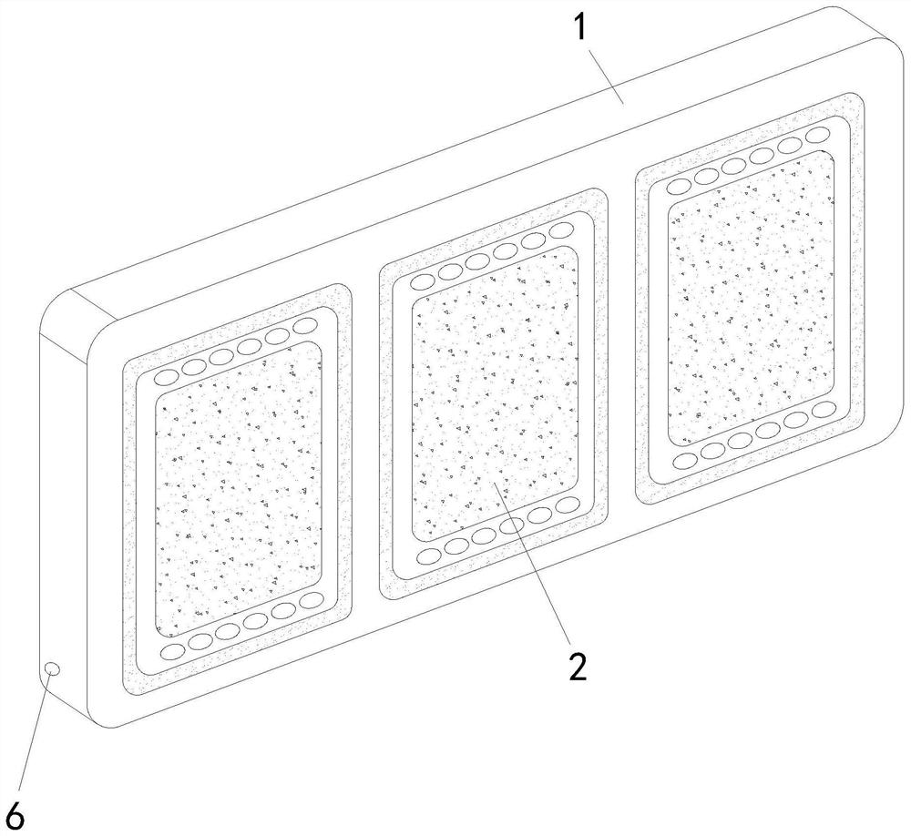
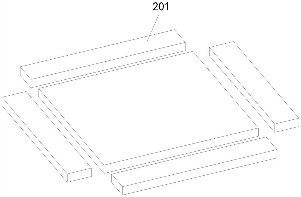
[0035] like Figure 1 to Figure 9 As shown, the medium and high frequency sound box with multiple magnets according to the present invention includes a box body 1, a speaker 2 is installed inside the box body 1, and the speaker 2 includes a magnet group 201, a washer, a basin frame, a voice coil, a spring Wave, sound cone and dust cover. The magnet group 201 includes a main magnet and four sub-magnets. The sub-magnets are placed around the main magnet. During operation, the magnet group 201 is installed to replace the U iron in the traditional speaker structure. The thickness can be reduced, so that the speaker can sound forward, the high frequency is not attenuated, and the sound quality will be more natural. Road distortion, while the power increases.

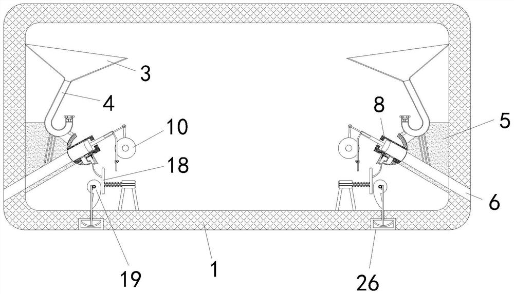
[0036] A water collecting plate 3 is installed inside the box body 1. The water collecting plate 3 includes a hydrophilic coating 301 and a hydrophobic coating 302. The hydrophilic coating 301 and the hydrophobic coating 302...

Embodiment 2

[0045] like Figure 10As shown, Comparative Example 1, in which another embodiment of the present invention is: the pressure plate 24 is rotatably installed on the active plate 18, a return spring is installed on the pressure plate 24, and the inside of the active plate 18 is rotated and installed to block the pressure plate 24. When the driving wheel 10 does not work and remains stationary, the pressing rod 30 fixes the left end of the turning plate 29 and moves to the left on the active plate 18 When the pressure plate 24 is stuck by the rotating plate 29, the pressure plate 24 will not rotate, and the lift plate 22 and the baffle plate 23 can be pulled smoothly; when the driving wheel 10 rotates and drives the piston cylinder 8 to swing, the pressure rod 30 Staggered from the rotating plate 29, the piston cylinder 8 drives the baffle plate 23 and the lifting plate 22 to swing together. Since the rotating plate 29 is no longer held by the pressure rod 30, the rotating plate ...


PUM


Abstract

The invention belongs to the field of sound boxes, in particular to a medium and high frequency sound box with multiple magnets, comprising a box body, a speaker comprising a magnet group, the magnet group comprising a main magnet and four sub-magnets, and the sub-magnets are placed around the main magnet, A water collecting plate is installed inside the box body. The water collecting plate includes a hydrophilic coating and a hydrophobic coating. A detection tube is connected to the bottom of the water collecting plate. The outlet of the side wall of the box body; by setting the water collecting plate, the hydrophilic coating and the hydrophobic coating make the water in the air in the box condense into water droplets and discharge, and extract and discharge the water in the air in the box, so as to achieve the The effect of dehumidification and drying, when the humidity is too high, the water collected in the detection tube is too much, so that the conductive sheet is in contact with the switch key, and the dehumidification component is activated. There is no need to install an additional electronic detection device, which reduces the use cost and saves the power consumption.

Description

technical field [0001] The invention belongs to the field of sound boxes, in particular to a medium and high frequency sound box with multiple magnets. Background technique [0002] In the prior art, the medium and high frequency speakers applied to OLED (OLED is Organic Light-Emitting Diode, the full name is "Organic Light Emitting Diode", which is a display screen technology), generally use a relatively thick traditional cone speaker box facing downwards. This method will lead to serious attenuation of the high frequency effect of the speaker. In order to improve the sound quality, most companies in the industry generally adjust the high frequency through a graphic equalizer. This method makes the high frequency sound very stiff and does not Naturally, it also increases the cost of the product. [0003] There are also some technical solutions about speakers in the prior art. For example, a Chinese patent with an application number of 202010478970.8 discloses a smart combi...

Claims


Application Information

Patent Timeline
Patent Type & Authority Patents(China)
IPC IPC(8): H04R1/02H04R9/06H04R9/02B01D53/26
CPCH04R1/028H04R9/06H04R9/02B01D53/26H04R2201/02
Inventor 蒋加星蔡禄军叶卫华
Owner WUXI JIEFU ELECTROACOUSTIC
Learn More