VR device having eye massage and lens cleaning functions

A lens and function technology, applied in the field of VR equipment with eye massage and lens cleaning functions, can solve problems such as reducing the practicability and reliability of the equipment, easily accumulating debris and dust on the lens, affecting visual effects, etc., to protect eyesight. , the effect of relieving visual fatigue and improving safety

Inactive Publication Date: 2018-01-09
JINJIANG SULONG ELECTRONICS TECH CO LTD
0 Cites 11 Cited by

AI-Extracted Technical Summary

Problems solved by technology

[0003] At present, VR devices are widely used in various fields of life. However, there are still some problems in actual use. For example, after a long-term use of VR devices worn on the eyes, the lens tends to accumulate debris and dust, which affects vision....

Method used

Compared with the prior art, in the VR equipment with eye massage and lens cleaning functions, the lens 2 can be scrubbed through the cleaning mechanism to make it clean, and a power source is used through the massage mechanism, Massage the eye sockets and Jingming points a...

Abstract

The invention relates to a VR device with functions of eye massage and lens cleaning, which includes a main body, a lens, a fixing belt, a central control mechanism, a cleaning mechanism and a massage mechanism. The cleaning mechanism includes a power component and a swing component, and the massage mechanism includes a moving component and a massage mechanism. The lifting assembly includes a driving unit and a reciprocating unit, and the lifting assembly includes a lifting unit and a fastening unit. In the VR device with eye massage and lens cleaning functions, the lens can be cleaned and cleaned through the cleaning mechanism. Through the massage mechanism, a power source is used to massage the eye socket and Jingming point at the same time, and the eyes Massaging and relaxing relieves the visual fatigue caused by wearing VR equipment for a long time, protects the user's eyesight, saves power costs, improves the massage effect, and greatly improves the practicability and reliability of the equipment.

Application Domain

Devices for pressing relfex pointsCleaning using tools +1

Technology Topic

Camera lensEngineering +3

Image

  • VR device having eye massage and lens cleaning functions
  • VR device having eye massage and lens cleaning functions
  • VR device having eye massage and lens cleaning functions

Examples

  • Experimental program(1)

Example Embodiment

[0033] The present invention is described in further detail now in conjunction with accompanying drawing. These drawings are all simplified schematic diagrams, which only illustrate the basic structure of the present invention in a schematic manner, so they only show the configurations related to the present invention.
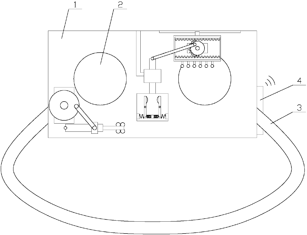
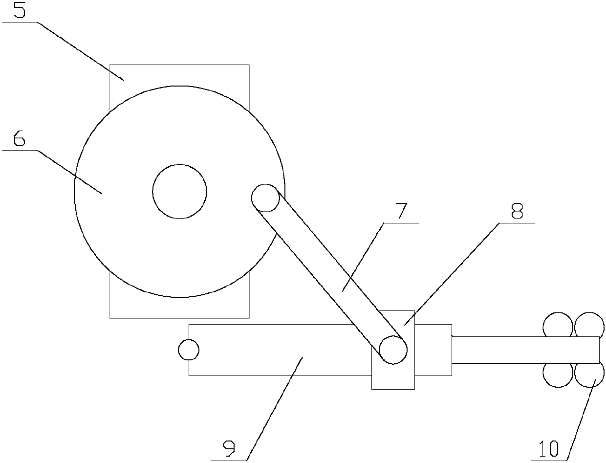
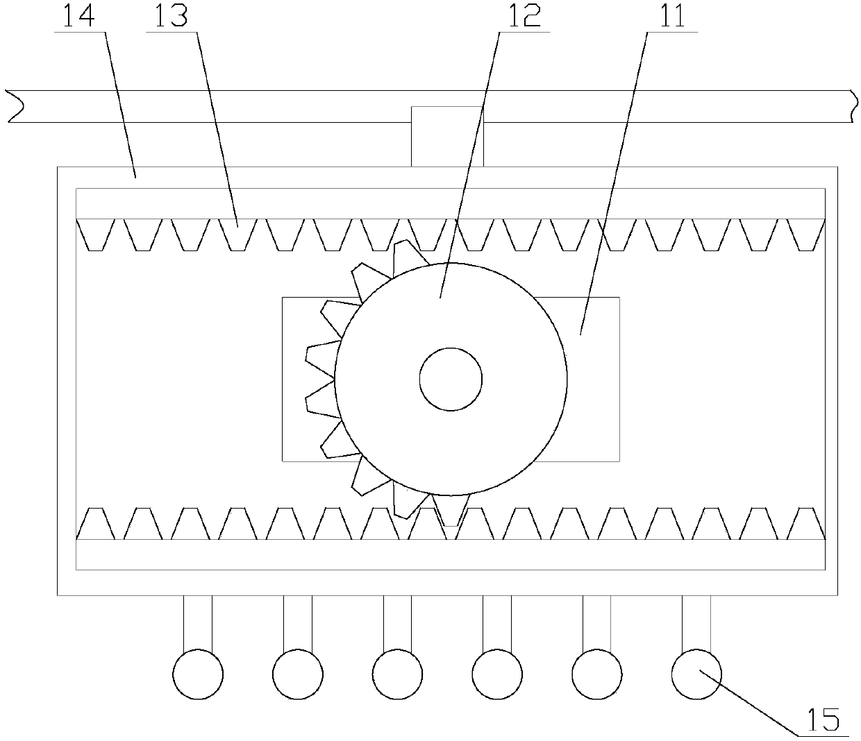
[0034] like Figure 1-Figure 7 As shown, a VR device with eye massage and lens cleaning functions includes a main body 1, a lens 2, a fixing belt 3, a central control mechanism, a cleaning mechanism and a massage mechanism, the lens 2 is arranged inside the main body 1, and the The fixing belt 3 is arranged on the main body 1, the central control mechanism is arranged on one side of the main body 1, the cleaning mechanism is arranged on one side of the lens 2, the massage mechanism is arranged inside the main body 1, and the cleaning mechanism Both the massage mechanism and the central control mechanism are electrically connected;
[0035] The massage mechanism includes a moving assembly and a lifting assembly, the moving assembly is arranged above the lens 2, the lifting assembly is arranged between the two lenses 2, and the moving assembly is in transmission connection with the reciprocating assembly;
[0036] The moving assembly includes a drive unit and a reciprocating unit, the drive unit is connected to the reciprocating unit, the drive unit includes a second motor 11 and a half gear 12, and the second motor 11 is horizontally arranged inside the main body 1, so The second motor 11 is connected with the transmission of the half gear 12;
[0037]The reciprocating unit includes two bar gears 13, a moving frame 14 and several massage balls 15, the moving frame 14 is horizontally arranged above the lens 2, the moving frame 14 slides inside the main body 1, each massage ball 15 Evenly distributed below the moving frame 14, two bar gears 13 are horizontally arranged on the upper and lower sides of the inner wall of the moving frame 14 respectively, the two bar gears 13 are symmetrical about the moving frame 14, and the half gear 12 is arranged on two Between the bar gears 13, the half gear 12 meshes with the bar gears 13;
[0038] When it is necessary to massage the eye sockets, at this moment, the second motor 11 starts, and the half gear 12 rotates thereupon, because the half gear 12 meshes with the bar gear 13, so the half gear 12 will drive the moving frame during the rotation process. 14 moves back and forth, the moving frame 14 will drive the massage ball 15 below to reciprocate and massage the eye sockets, massage and relax the eyes, relieve the visual fatigue caused by wearing VR equipment for a long time, and protect the user's vision. Greatly improve the practicability and safety of the equipment.
[0039] The lifting assembly includes a lifting unit and a fastening unit, the fastening unit is arranged on the lifting unit, and the lifting unit is in transmission connection with the fastening unit;
[0040] The lifting unit includes a connecting rod 16, a lifting rod 17 and a fixed plate 19, the fixed plate 19 is vertically arranged inside the main body 1 and is located between the two lenses 2, the lifting rod 17 is vertically arranged, and the The lower end of the lifting plate is connected with the fixed plate 19, the upper end of the lifting rod 17 is hinged with one end of the connecting rod 16, and the other end of the connecting rod 16 is hinged with the half gear 12 away from the center of circle;
[0041] The fastening unit is arranged on the fixed plate 19, the fastening unit includes two rotating units, the two rotating units are respectively arranged on both sides of the fixed plate 19 and symmetrical about the fixed plate 19, and the rotating unit includes an electromagnet 20. The fixed rod 21 and the massage block 22, the fixed plate 19 is provided with a groove, the groove is horizontally arranged, the electromagnet 20 is horizontally arranged inside the groove and slides in the groove, the fixed Rod 21 is vertically arranged on one side of electromagnet 20, and the middle part of described fixed rod 21 is hinged with fixed plate 19, and one side of the lower end of described fixed rod 21 is hinged with electromagnet 20, and described massage block 22 is arranged on the fixed On one side of the upper end of the rod 21 , the massage block 22 is located between the two fixed rods 21 .
[0042] When it is necessary to massage Jingming acupoint, at this time, the electromagnet 20 is energized, and the two electromagnets 20 have opposite magnetism and slide in opposite directions in the groove. The fixed rod 21 rotates around the hinge in the middle, and the two massage The blocks 22 are close to each other and lean against the Jingming point at the bridge of the nose. At the same time, the half gear 12 drives the connecting rod 16 to rotate, and the connecting rod 16 drives the elevating rod 17 to move up and down, thereby driving the fixed plate 19 to move up and down. Therefore, the massage block 22 also moves with the Move up and down to massage the Jingming acupoint to relieve visual fatigue. In addition, during the massage process, only one power source is used, but the eye socket and Jingming acupoint are massaged at the same time, which saves power costs and improves the massage effect. the usability of the equipment.
[0043] As a preference, when the lens 2 needs to be cleaned, at this moment, the first motor 5 starts, the drive wheel 6 rotates thereupon, the drive wheel 6 drives the connecting rod 7 to rotate, and the connecting rod 7 slides on the cylinder 9 with the collar 8 At the same time, the cylinder 9 will rotate around the hinge. During the swinging process, the cylinder 9 can move over the length of the control output shaft, so that the cleaning brush 10 can fully contact the lens 2 for cleaning, so that the lens 2 is clean and convenient. Watching, enhances the visual experience. The cleaning mechanism includes a power assembly and a swing assembly, the power assembly is in transmission connection with the swing assembly, the power assembly includes a first motor 5 and a driving wheel 6, and the first motor 5 is horizontally arranged inside the main body 1, so The first motor 5 is in transmission connection with the drive wheel 6. The swing assembly includes a connecting rod 7, a collar 8, a cylinder 9 and a cleaning brush 10. The cylinder 9 is horizontally arranged below the lens 2. The cylinder 9 is connected to the main body 1, the cleaning brush 10 is arranged on the output shaft of the cylinder 9, the collar 8 is sleeved on the cylinder 9, the collar 8 slides on the cylinder 9, and one end of the connecting rod 7 is connected to the The collar 8 is hinged, and the other end of the connecting rod 7 is hinged away from the center of the circle with the driving wheel 6 .
[0044] As a preference, in order to detect whether the massage block 22 is against the acupuncture point at the bridge of the nose, the electromagnet 20 moves, so that the spring 23 is compressed, and the spring 23 transmits the active force to the pressure sensor 24. Through the detection of the pressure sensor 24, it is judged whether it is against the acupuncture point. acupuncture points. The fixed plate 19 is also provided with a detection unit, the detection unit includes a pressure sensor 24 and a spring 23, the pressure sensor 24 is arranged on the fixed plate 19, the spring 23 is horizontally arranged, and the pressure sensor 24 passes through the spring 23 links to each other with fixed rod 21.
[0045] As a preference, in order to move the moving frame 14 horizontally and stably, a balance unit is provided above the moving frame 14, and the balancing unit includes a moving block 25 and a dovetail groove 26, and the dovetail groove 26 is horizontally arranged on the main body 1. Inside, the moving block 25 is matched with the dovetail groove 26 , the moving frame 14 slides inside the dovetail groove 26 , and the moving block 25 is connected with the moving frame 14 .
[0046] Preferably, in order to make the elevating rod 17 move up and down stably, the elevating rod 17 is provided with a sleeve 18 , the sleeve 18 is fixed inside the main body 1 , and the elevating rod 17 is slidably connected with the sleeve 18 .
[0047] Preferably, in order to make the first motor 5 work accurately for a long time, the first motor 5 is a servo motor.
[0048] Preferably, the central control mechanism includes a display interface 27, control buttons 28 and status indicator lights 4, and the display interface 27, control buttons 28 and status indicator lights 4 are all electrically connected to the PLC.
[0049] Preferably, in order to observe more clearly, the display interface 27 is a liquid crystal display.
[0050] Preferably, in order to facilitate key operation, the control key 28 is a light touch key.
[0051] Preferably, in order to be able to remotely control the device, an antenna is provided inside the main body 1, and the antenna is electrically connected to the PLC.
[0052] Compared with the prior art, in this VR device with eye massage and lens cleaning functions, the lens 2 can be cleaned and cleaned through the cleaning mechanism, and a power source is used through the massage mechanism to clean the eye sockets and Massage Jingming point at the same time, massage and relax the eyes, relieve the visual fatigue caused by wearing VR equipment for a long time, protect the user's vision, save power costs, improve the massage effect, and greatly improve the practicability of the device and reliability.
[0053] Inspired by the above-mentioned ideal embodiment according to the present invention, through the above-mentioned description content, relevant workers can make various changes and modifications within the scope of not departing from the technical idea of ​​the present invention. The technical scope of the present invention is not limited to the content in the specification, but must be determined according to the scope of the claims.

PUM

no PUM

Description & Claims & Application Information

We can also present the details of the Description, Claims and Application information to help users get a comprehensive understanding of the technical details of the patent, such as background art, summary of invention, brief description of drawings, description of embodiments, and other original content. On the other hand, users can also determine the specific scope of protection of the technology through the list of claims; as well as understand the changes in the life cycle of the technology with the presentation of the patent timeline. Login to view more.

Similar technology patents

Automatic pencil with myopia-preventing alarm

InactiveCN105620114Aprotect eyesight
Owner:GUCHENG COUNTY THIRD MIDDLE SCHOOL

Illumination control method and device, lamp and storage medium

ActiveCN111726919AProtect eyesight
Owner:MIDEA INTELLIGENT LIGHTING & CONTROLS TECH CO LTD

Display which can be automatically turned off

InactiveCN107783593Aprotect eyesight
Owner:XIANGYANG NO 42 MIDDLE SCHOOL

Desk & chair having function of correcting sitting posture

InactiveCN105534049AProtect eyesightPrevent hunchback
Owner:李江涛

Classification and recommendation of technical efficacy words

  • Protect eyesight
  • Improve practicality

Method and mobile terminal for active protection of eyesight

ActiveCN103442127AProtect eyesightavoid all-in
Owner:GUANGDONG OPPO MOBILE TELECOMM CORP LTD

Display adjustment method and device, electronic equipment and storage medium

InactiveCN111414114Areduce irritationProtect eyesight
Owner:BEIJING XINWANG RUIJIE NETWORK TECH CO LTD

Device and method for constructing self-adaptive graphic user interface (GUI)

ActiveCN102193786ASolve control intersection and information truncation problemsImprove practicality
Owner:INDUSTRIAL AND COMMERCIAL BANK OF CHINA

Photographing method and terminal

Owner:GUANGDONG OPPO MOBILE TELECOMM CORP LTD
Why Eureka
Try Eureka