Permanent magnet synchronous motor

A technology of permanent magnet synchronous motors and permanent magnets, applied in synchronous machines, synchronous machine parts, electrical components, etc., can solve the problems of mechanical deformation of magnetic paths, magnetic flux leakage, and low utilization rate of permanent magnet materials, and achieve reliable structure, Avoid the effects of mechanical deformation

Pending Publication Date: 2018-01-09
河南全新机电设备有限公司
View PDF0 Cites 0 Cited by
  • Summary
  • Abstract
  • Description
  • Claims
  • Application Information

AI Technical Summary

Problems solved by technology

[0004] There are two types of permanent magnets embedded in the rotor of permanent magnet synchronous motors: surface-mounted and embedded; but for high-power permanent magnet synchronous motors with external permanent magnets, the magnetic fields of permanent magnets between adjacent two poles are easily connected directly, wh

Method used


Image

  • Permanent magnet synchronous motor
  • Permanent magnet synchronous motor
  • Permanent magnet synchronous motor

Examples


Embodiment Construction

[0011] Embodiments are described in detail in conjunction with the accompanying drawings,

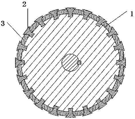
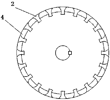
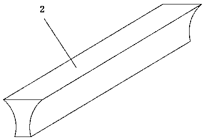
[0012] A permanent magnet synchronous motor, which includes a rotor core 1, and a special-shaped cage bar 2 is arranged on the outer side of the rotor core along the rotor axial direction, and the bottom corner of the centripetal part of the special-shaped cage bar is stuck on the silicon steel sheet on the rotor core In the slot corresponding to the shape, the two ends of the special-shaped cage are fixedly connected with the end ring 4, and the permanent magnet 3 is inlaid between the special-shaped cage, and the magnetic properties of the permanent magnets between adjacent two poles are opposite. The polarities of the permanent magnets between the special-shaped bars are the same; the section of the special-shaped cage bars described in this embodiment is a hyperbola.

[0013] The magnetization direction of each permanent magnet stuck in the adjacent cage of the opposite sex is chamf...


PUM


Abstract

The invention discloses a permanent magnet synchronous motor. The technical solution of the invention is a permanent magnet synchronous motor, which includes a rotor iron core, and a special-shaped cage bar is arranged on the outer side of the rotor iron core along the rotor axial direction. The special-shaped cage bar The bottom corner of the centripetal part is stuck in the slot corresponding to the shape of the silicon steel sheet on the rotor core. The two ends of the special-shaped cages are fixedly connected with the end rings. The magnetism of the permanent magnets is opposite, and the polarities of the permanent magnets are the same between adjacent I-shaped special-shaped bars in one pole area. The beneficial effect of the invention is that it can effectively avoid the irreversible mechanical deformation of the magnetic path being squeezed, and the structure is reliable.

Description

technical field [0001] The invention relates to a motor, in particular to a high-power permanent magnet synchronous motor. Background technique [0002] Permanent magnet motors have the advantages of low loss and high efficiency, and are used more and more widely today when energy conservation and environmental protection are increasingly valued. Such as: fans, water pumps, compressors, etc. in continuous, constant speed and unidirectional applications, ordinary asynchronous motors are gradually being replaced by permanent magnet motors due to the waste of electric energy due to efficiency, power factor and other reasons. At the same time, the operating speed of many industrial machines needs to be set and adjusted arbitrarily, but the accuracy of speed control is not high. Due to the advantages of small size, high efficiency and energy saving, permanent magnet synchronous motors are gradually becoming the main products in this field. [0003] At present, high-power permane...

Claims


Application Information

Patent Timeline
IPC IPC(8): H02K21/46H02K21/02
CPCY02T10/64
Inventor 尚勤贵尚金鸽尚金锋
Owner 河南全新机电设备有限公司
Why Eureka
Try Eureka